









Last Updated on 2026-08-11 by Usine de solénoïdes
A common problem in OEM electromagnetic actuator development is surprisingly difficult to diagnose: a custom solenoid passes the supplier’s bench test, meets the specified voltage and force requirements, and appears fully functional as an individual component—but fails, becomes inconsistent, or performs poorly after it is installed into the customer’s actual product.
This situation can be frustrating for both the purchasing team and the engineering department. The supplier may insist that the sample passed inspection, while the OEM team observes weak actuation, slow response, excessive noise, sticking, incomplete stroke, overheating, or intermittent operation on the assembly line.
The important engineering principle is that a solenoid does not operate in isolation once it becomes part of a finished product. Its actual performance depends on the complete electromechanical system, including mounting tolerances, alignment, load conditions, power supply, wiring, temperature, surrounding components, friction, vibration, and the way the customer’s assembly process constrains the actuator.
This article explains why a custom solenoid can pass a laboratory bench test but fail during real-world integration, how to identify the root cause, how to design a more reliable validation process, and how OEM buyers can select a professional custom solenoid factory capable of supporting the complete application rather than simply producing components to drawings.
1. Custom Solenoid Bench Testing vs. Real Application Testing
The first distinction engineers should make is between component-level validation et system-level validation.
A typical supplier bench test may look like this:
- Solenoid mounted freely
- Correct rated voltage applied
- No side load on the plunger
- Controlled ambient temperature
- Short operating duration
- Correct nominal stroke
- Ideal wiring
- No vibration
- No neighboring mechanical components
Under these conditions, the custom solenoid may perform exactly as expected.
However, the same solenoid installed in a finished machine may experience:
- Side loading
- Misalignment
- Restricted movement
- Different operating voltage
- Higher temperature
- Longer duty cycle
- Additional mechanical load
- Contamination
- Vibration
- Tight housing tolerances
- Assembly stress
Therefore, a successful bench test does not automatically prove successful system integration.
Key Engineering Principle: A solenoid should be validated under the same mechanical, electrical, thermal, and environmental conditions that it will experience in its final application.
2. Custom Solenoid Failure Caused by Mechanical Misalignment
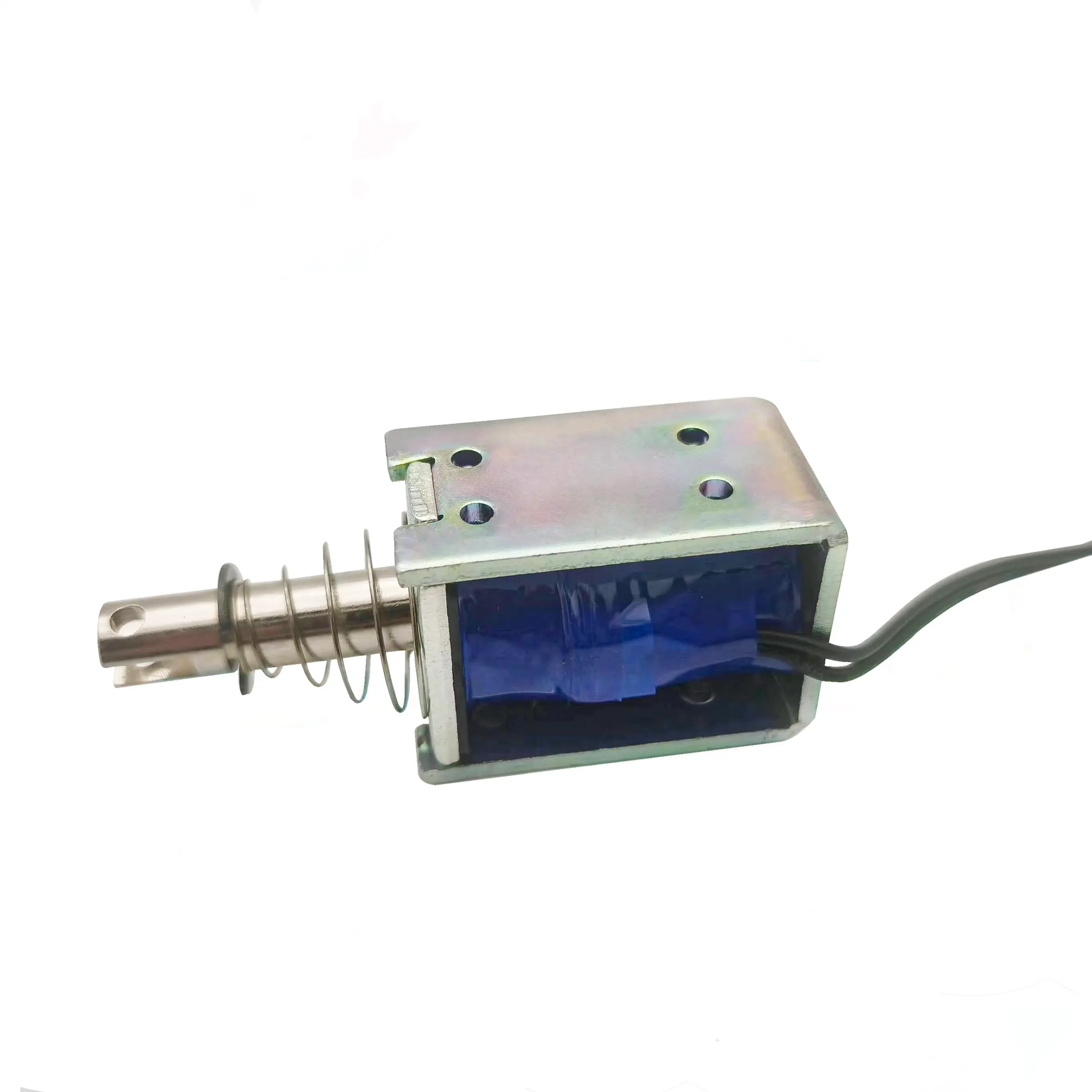
One of the most common reasons a custom solenoid performs differently after assembly is plunger misalignment.
A solenoid is designed around a specific magnetic and mechanical axis. Ideally, the plunger moves concentrically inside the guide sleeve.
During actual assembly, however, the housing, mounting bracket, guide hole, shaft, or connected mechanism may introduce a small angular or lateral offset.
Even a relatively small amount of misalignment can create additional friction.
The result can be:
Higher friction → higher required force → slower movement → incomplete stroke → unstable operation
The supplier’s free-standing bench test may never reveal this problem because the plunger is perfectly aligned.
Exemple
A solenoid produces 8 N of available force.
The customer’s mechanism requires 5 N under ideal conditions.
This appears to provide sufficient margin.
But after assembly:
- Side load adds 1.5 N
- Seal friction adds 0.8 N
- Mechanical linkage adds 1 N
The actual requirement becomes approximately 8.3 N.
The actuator now operates at or beyond its practical force limit.
Engineering Solution
Un professionnel custom solenoid manufacturer should evaluate:
- Plunger concentricity
- Guide clearance
- Mounting tolerance
- Side-load sensitivity
- Shaft alignment
- Mechanical linkage geometry
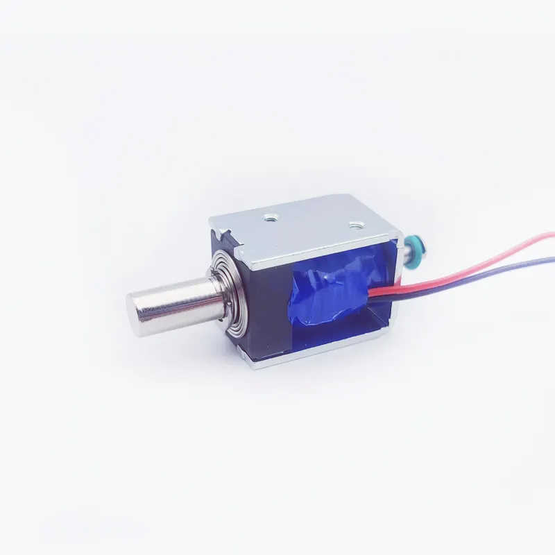
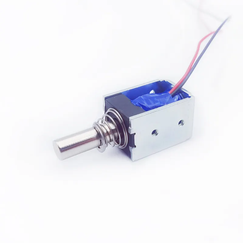
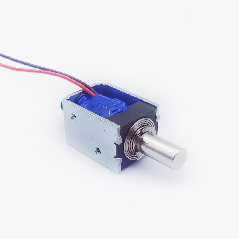
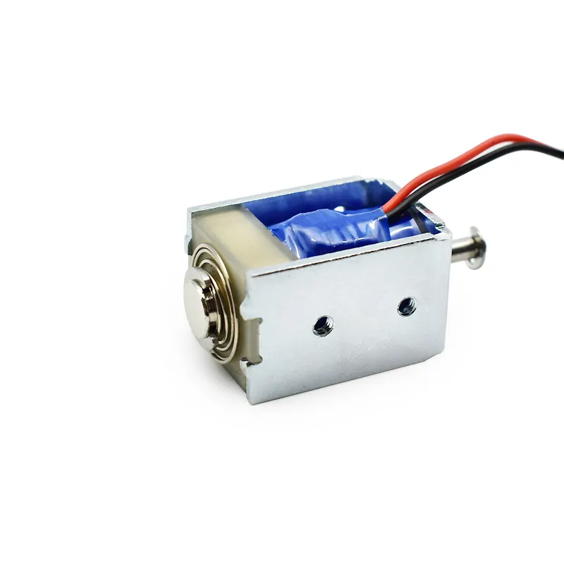
Whenever possible, the solenoid should be tested together with the customer’s actual mounting structure.
3. Custom Solenoid Force Is Not Constant Throughout the Stroke
Another common misconception is that a solenoid has one fixed force value.
In reality, electromagnetic force changes significantly with plunger position.
The force is generally strongest when the magnetic air gap is small and decreases as the plunger moves away from the energized magnetic circuit.
This means that a custom solenoid specified as “10 N force” is not sufficiently defined.
Engineers need to know:
- Force at what stroke?
- Starting force?
- End-of-stroke force?
- Holding force?
- Operating voltage?
- Temperature?
- Duty cycle?
Force-Stroke Example
| Plunger Position | Typical Relative Force |
|---|---|
| 0 mm | Lower |
| 1 mm | Moderate |
| 3 mm | Higher |
| Near End Stroke | Highest |
The exact curve depends on the magnetic circuit and geometry.
If the assembly mechanism requires high force at the beginning of the stroke, but the supplier’s test only measures force near the end of the stroke, the sample may technically pass the specification while still failing in the actual machine.
Best Practice: Always evaluate the complete force-stroke curve rather than relying on one force value.
4. Custom Solenoid Installation Tolerances Can Change Performance
Tolerance stack-up is often underestimated during product development.
Consider a system containing:
- Solenoid housing tolerance
- Mounting bracket tolerance
- Plunger tolerance
- Guide sleeve tolerance
- Shaft tolerance
- Linkage tolerance
- Assembly hole tolerance
Each individual tolerance may be acceptable.
However, when combined, they can shift the actuator away from its ideal position.
This is called tolerance stack-up.
Exemple
| Component | Potential Offset |
|---|---|
| Mounting bracket | ±0.20 mm |
| Housing | ±0.10 mm |
| Guide structure | ±0.10 mm |
| Linkage | ±0.15 mm |
| Assembly hole | ±0.15 mm |
The resulting system-level variation may be much greater than the tolerance of the solenoid itself.
Un professionnel usine d'électroaimants should therefore consider the customer’s complete tolerance chain rather than optimizing the actuator independently.


5. Custom Solenoid Electrical Conditions May Differ on the Assembly Line
A bench test often uses a laboratory power supply with stable voltage.
Production equipment may not.
During actual operation, the custom solenoid may experience:
- Voltage drop
- Long cable resistance
- Connector resistance
- Switching losses
- Power supply fluctuations
- Shared power circuits
- Commande PWM
- Driver limitations
For example, a nominal 24 V solenoid may receive only 20–21 V at the coil during peak operation because of wiring and connector losses.
Because solenoid force depends strongly on coil current and magnetic flux, this voltage reduction can have a significant impact.
Recommended Validation
Measure voltage directly across the solenoid terminals during actual operation.
Do not simply measure the output voltage of the power supply.
This simple diagnostic step can reveal problems that component-level testing cannot detect.
6. Custom Solenoid Temperature Can Change Force and Response
Temperature is another major difference between bench testing and real applications.
Copper resistance increases as temperature rises.
As coil temperature increases:
Higher resistance → lower current at the same voltage → reduced magnetic force
At the same time, thermal expansion may change:
- Plunger clearance
- Sleeve dimensions
- Housing dimensions
- Mechanical alignment
This can increase friction or alter the magnetic air gap.
A solenoid that works perfectly at 25°C may behave differently after operating continuously inside a machine at 70°C or higher.
Professional Validation Should Include
- Cold-start testing
- Hot-start testing
- Fonctionnement continu
- Maximum ambient temperature
- Maximum coil temperature
- Worst-case voltage
- Maximum mechanical load
7. Custom Solenoid Duty Cycle Is Critical
A common supplier test might energize a solenoid for a few seconds and then allow it to cool.
The production machine may operate it hundreds or thousands of times per hour.
These are completely different conditions.
The key parameters include:
- Energization duration
- De-energization duration
- Cycles per minute
- Continuous vs intermittent duty
- Température ambiante
- Maximum acceptable coil temperature
A custom solenoid designed for intermittent duty should not automatically be used for continuous operation.
The customer’s actual duty cycle should be provided to the manufacturer during the design stage.
8. Custom Solenoid Friction and Lubrication Can Change During Assembly
Friction is often invisible during supplier bench testing but becomes significant after integration.
Potential causes include:
- Plunger side loading
- Excessive guide interference
- Contamination
- Incorrect lubricant
- Assembly particles
- Seal compression
- Surface coating differences
For example, a nickel-plated plunger operating freely in a supplier’s clean test fixture may encounter increased friction when installed into a customer’s tighter guide structure.
The correct engineering approach is not simply to add more lubrication.
The manufacturer should evaluate the entire tribological system:
Plunger material + plating + guide material + surface roughness + clearance + lubricant + temperature
This is especially important for high-cycle solénoïde électromagnétique applications.
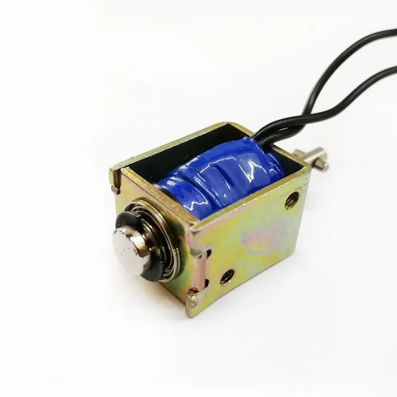

9. Custom Solenoid Integration Requires Testing the Complete Mechanical Load
A solenoid should not be tested only with an artificial load if its actual application contains a complicated mechanical mechanism.
A customer’s mechanism may include:
- Springs
- Levers
- Gears
- Cam mechanisms
- Seals
- Latches
- Linkages
These components can produce nonlinear loads.
For example, a spring may require significantly more force near one end of the stroke than another.
Therefore, the ideal validation method is to test the custom solenoid with the customer’s actual load profile.
Recommended Test Sequence
- Test the solenoid independently.
- Test it with a simulated load.
- Test it with the actual mechanical assembly.
- Test worst-case tolerance combinations.
- Test hot and cold conditions.
- Test minimum operating voltage.
- Perform lifecycle testing.
This staged approach provides much more reliable engineering data.
10. Why Supplier Samples Sometimes Pass but Production Units Fail
Another important issue is the difference between prototype quality and mass-production consistency.
A supplier may manually select the best components for samples.
For example:
- Best plunger
- Best coil resistance
- Best spring
- Best dimensional fit
The prototype then performs extremely well.
But mass production contains normal manufacturing variation.
If the design has insufficient tolerance margin, production units may show:
- Different force
- Different response time
- Different current
- Different friction
- Different noise
This is why a professional usine de solénoïdes should validate both the design and the manufacturing process.
Key Concept
Prototype validation ≠ Mass-production validation
The supplier must demonstrate that the design remains robust across the complete manufacturing tolerance range.
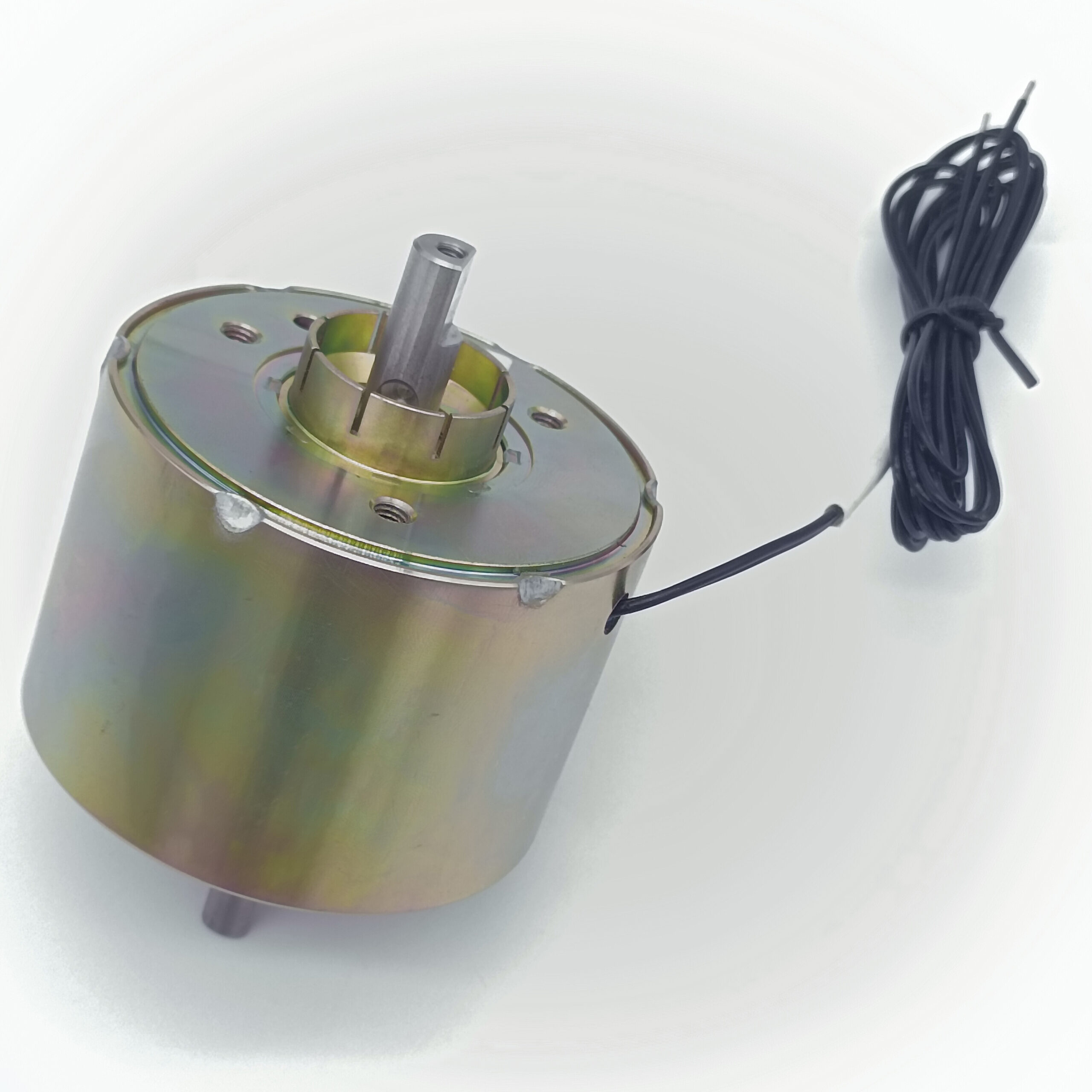
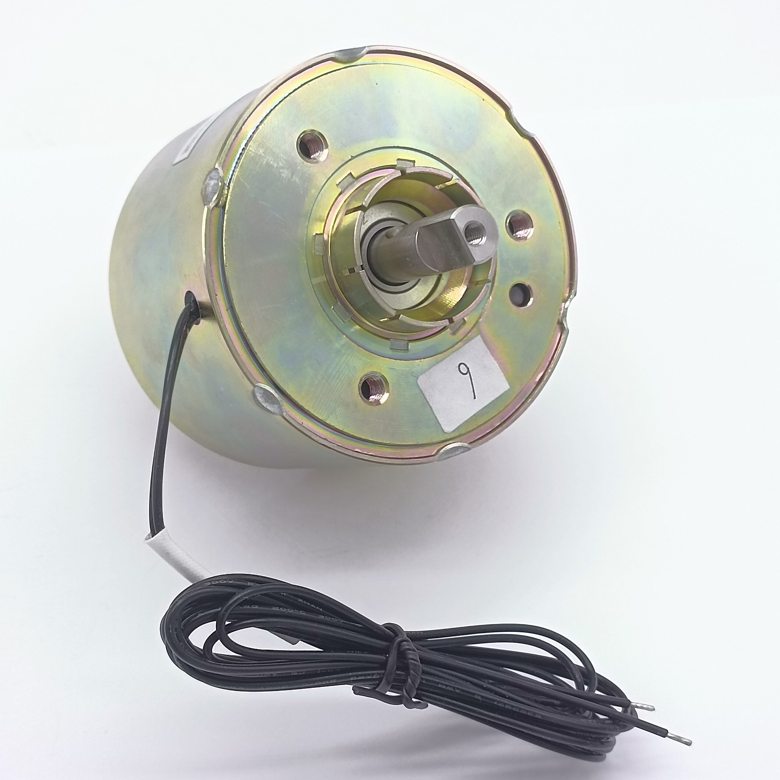
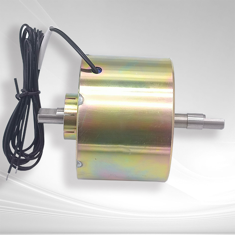

11. How a Professional Custom Solenoid Factory Solves Integration Problems
When a customer reports that a sample works on the bench but fails in the machine, the correct response should be an engineering investigation—not simply a replacement shipment.
Un professionnel custom solenoid factory should analyze four categories.
Mechanical
- Alignment
- Side load
- Accident vasculaire cérébral
- Friction
- Tolerance stack-up
Electrical
- Tension
- Actuel
- Driver
- Wiring
- PWM
- Connector resistance
Thermal
- Température ambiante
- Coil temperature
- cycle de service
- Heat dissipation
Magnetic
- Force-stroke curve
- Air gap
- Core material
- Magnetic saturation
- Residual magnetism
This four-dimensional approach makes root-cause analysis much faster.
12. SF Custom Solenoid Engineering Approach
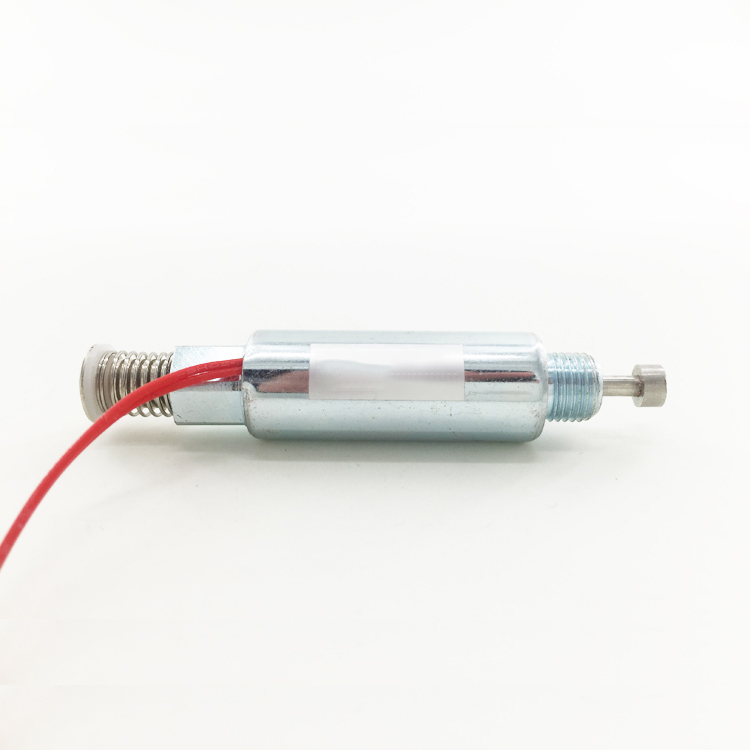
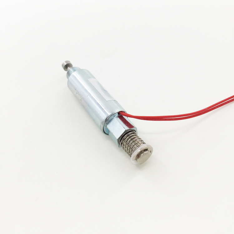
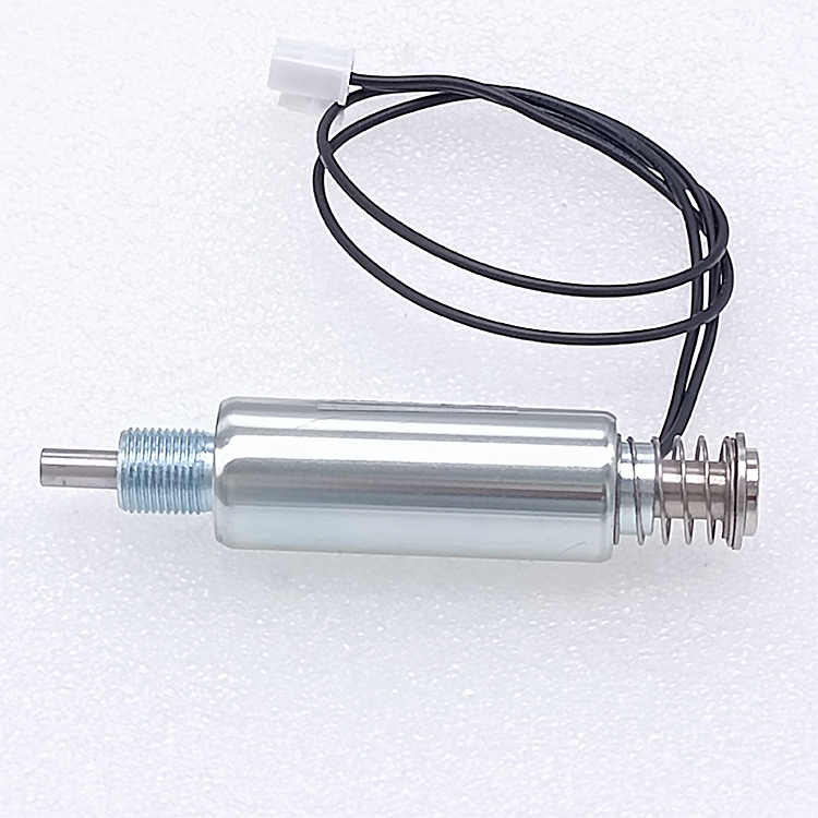
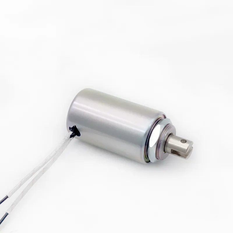
With more than 10 years of experience in customized electromagnet and solenoid manufacturing, SF understands that supplying a component is different from solving an application problem.
Our experienced engineering team works with customers to evaluate the complete operating environment.
SF’s 6,000㎡ manufacturing facility supports:
- Precision machining
- Coil winding
- Electromagnetic assembly
- Surface treatment
- Functional testing
- Prototype production
- Lifecycle validation
When developing a custom solenoid, our engineers can evaluate the customer’s:
- Force requirements
- Accident vasculaire cérébral
- Installation structure
- Operating voltage
- cycle de service
- Temperature
- Environmental conditions
- Expected service life
This application-driven approach helps reduce the risk of a product passing an isolated laboratory test but failing after integration.
SF has supported customized electromagnet solutions for brand customers in multiple industries, with products exported to more than 60 countries and regions.
13. How to Choose the Right Custom Solenoid Manufacturer
The right supplier should be evaluated on more than price and production capacity.
OEM buyers should consider at least these eight dimensions:
| Evaluation Dimension | What to Verify |
|---|---|
| Engineering | In-house experienced engineers |
| Magnetic Design | Force-stroke and magnetic circuit analysis |
| Mechanical Design | Tolerance and alignment optimization |
| Customization | Ability to develop from requirements |
| Testing | Force, voltage, temperature, lifecycle testing |
| Fabrication | CNC, winding, assembly and inspection |
| Quality | Process control and traceability |
| Application Support | Ability to test under actual operating conditions |
A supplier that simply manufactures according to a drawing may be adequate for simple applications.
For demanding applications, however, an experienced custom solenoid manufacturer is much more valuable because it can identify potential integration problems before mass production.
14. How OEM Buyers Can Prevent Custom Solenoid Integration Failures
Before approving a supplier, provide as much application information as possible.
Recommended Customer Input
Mechanical
- Available installation space
- Mounting method
- Accident vasculaire cérébral
- Load curve
- Alignment requirements
- Side loads
Electrical
- Tension nominale
- Minimum voltage
- Maximum voltage
- Driver type
- Peak current
- PWM parameters
Thermal
- Température ambiante
- cycle de service
- Maximum operating temperature
Environmental
- Humidity
- Dust
- Water
- Vibration
- Corrosive atmosphere
Reliability
- Target cycle life
- Failure criteria
- Maintenance requirements
The more accurately the manufacturer understands the final application, the more effectively it can engineer the custom solenoid.
A Solenoid Must Be Designed for the Application, Not Just the Test Bench
A custom solenoid can pass a conventional bench test and still fail during assembly line integration because the laboratory test may not reproduce the real operating environment.
The most common causes include:
- Mechanical misalignment
- Side loading
- Force-stroke mismatch
- Tolerance stack-up
- Voltage drop
- Increased operating temperature
- Incorrect duty cycle
- Friction and lubrication changes
- Production variation
- Differences between laboratory and actual mechanical loads
The solution is not simply to make the solenoid “stronger.” Increasing force without understanding the actual failure mechanism can increase power consumption, heat generation, noise, and cost while leaving the underlying integration problem unresolved.
A better approach is application-driven solenoid engineering.
The manufacturer should analyze the magnetic circuit, mechanical structure, electrical system, thermal environment, tolerances, and lifecycle requirements as one integrated system.
For OEM customers, this is why choosing the right custom solenoid factory matters.
With more than 10 years of experience, an experienced engineering team, a 6,000㎡ manufacturing facility, comprehensive customization capabilities, and products exported to 60+ countries and regions, SF provides customized electromagnet and solenoid solutions for global brand customers.
Rather than treating the solenoid as an isolated component, SF focuses on the complete application—from electromagnetic design and mechanical optimization to prototype validation, manufacturing, and lifecycle testing.
The best custom solenoid is not the one that simply passes a bench test. It is the one that continues to perform reliably after it becomes part of the customer’s real product.
FAQ
Why can a custom solenoid pass a bench test but fail during assembly line integration?
The most common reasons are mechanical misalignment, side loading, force-stroke mismatch, tolerance stack-up, voltage drop, temperature rise, incorrect duty cycle, increased friction, and differences between prototype and mass-production conditions.
How can the problem be prevented?
The custom solenoid should be validated under actual installation conditions, including the customer’s mechanical load, minimum operating voltage, temperature, duty cycle, tolerances, and expected lifecycle.
What should OEM buyers look for in a custom solenoid manufacturer?
They should evaluate engineering expertise, magnetic circuit design, mechanical tolerance analysis, customization capability, prototype development, production capacity, quality control, testing capabilities, and application-level technical support.
Why choose SF?
SF has more than 10 years of custom electromagnet manufacturing experience, an experienced engineering team, a 6,000㎡ manufacturing facility, extensive OEM customization experience, and exports to more than 60 countries and regions. Its application-driven engineering approach helps customers develop custom solenoid solutions that are designed not merely to pass laboratory testing, but to perform reliably in real-world assembly and operating environments.
Fabrication sur mesure de tous types d'électroaimants, contactez l'usine d'électroaimants SF WhatsApp +86 189 0261 1680