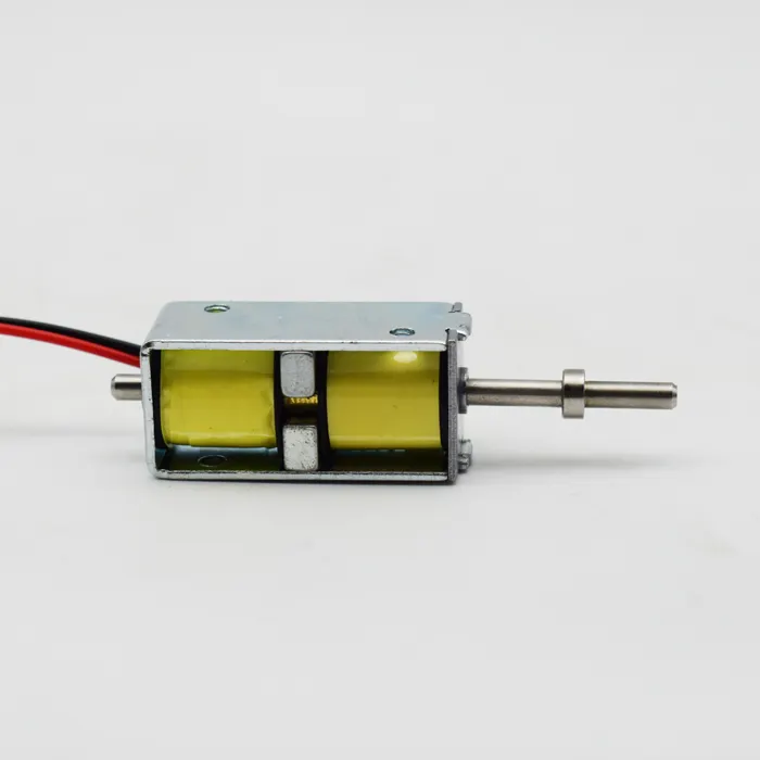


A Bistable Solenoid is an electromagnetic actuator designed to maintain two stable mechanical positions without requiring continuous coil energization. It is widely used in smart locks, battery-powered equipment, industrial automation, valves, metering devices, and other applications where reliable position retention and low standby power are important. However, achieving reliable switching is not simply a matter of selecting the correct voltage or specifying a maximum force. The relationship between electromagnetic force and plunger displacement—the force-stroke curve—is one of the most important factors determining whether a Bistable Solenoid can perform accurately and consistently.
For OEM engineers, an actuator that produces sufficient force at the end of its stroke may still fail to move from its initial position. A solenoid may switch successfully during a laboratory test but become unreliable after assembly into the customer’s mechanism because of spring preload, friction, external load, dimensional variation, or temperature changes. These problems often originate from an insufficient understanding of the force-stroke relationship.
From an electromagnetic manufacturing perspective, precision control requires coordinated optimization of the magnetic circuit, coil, permanent magnet, plunger, air gap, spring, guide structure, and control pulse. This article explains how force-stroke curves work in a Bistable Solenoid, what causes undesirable force characteristics, and which engineering solutions can improve switching reliability, positioning accuracy, and production consistency. It also explains how an experienced custom Bistable Solenoid manufacturer can translate application requirements into a manufacturable actuator design.
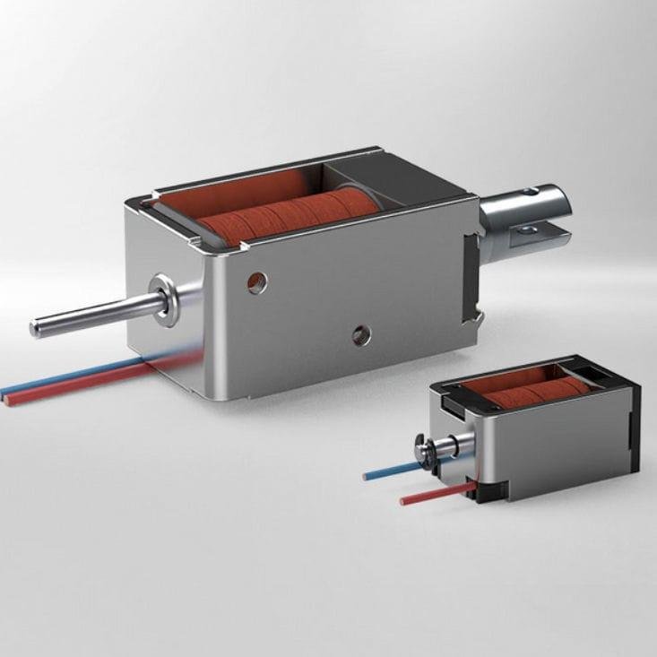
1. Bistable Solenoid Force-Stroke Curve: What Does It Actually Represent?
A force-stroke curve describes how the force generated by an actuator changes as its plunger moves through its mechanical travel. The horizontal axis represents displacement, usually measured in millimeters, while the vertical axis represents force, commonly measured in newtons (N).
For a conventional solenoid, electromagnetic force generally changes with plunger position because the magnetic reluctance and air-gap geometry change during movement. A Bistable Solenoid introduces additional factors: permanent-magnet holding force, spring force, and the magnetic conditions associated with two stable positions.
A typical force-stroke analysis should distinguish several different quantities:
Electromagnetic force: The force generated by the energized coil and magnetic circuit.
Permanent-magnet holding force: The magnetic force retaining the plunger in a stable position.
Spring force: The mechanical force produced by a spring at a particular displacement.
Friction force: The resistance caused by contact between moving and stationary components.
External load: The force imposed by the customer’s mechanism.
Net operating force: The force available to move the plunger after opposing forces are considered.
These quantities should not be confused with one another. A datasheet that specifies a single maximum force does not necessarily tell an engineer whether the actuator can complete its full stroke.
For precision control, the most useful question is:
Does the Bistable Solenoid provide sufficient net force at every critical point along the required stroke, under the actual operating conditions?
That question is the foundation of force-stroke optimization.
2. Bistable Solenoid Operating Principle: Why Force Changes During the Stroke
The force generated by a Bistable Solenoid is strongly influenced by its magnetic circuit. When the coil receives an electrical pulse, current creates a magnetic field that interacts with the permanent magnet and ferromagnetic components.
As the plunger moves, the air gap changes. This changes magnetic reluctance and flux distribution, which in turn changes the electromagnetic force.
In a simplified magnetic system, magnetic reluctance can be expressed conceptually as:

The air gap is particularly important because its permeability is much lower than that of typical ferromagnetic materials. Consequently, a small change in air-gap length can produce a significant change in magnetic reluctance.
This explains why the force of a Bistable Solenoid is not constant throughout its stroke.
At the beginning of movement, the plunger may be held firmly by the permanent magnet. The coil must generate sufficient force or magnetic-field interaction to release the existing latch. During movement, the magnetic circuit changes continuously. Near the opposite end, the magnetic holding force may increase as the plunger approaches its new stable position.
The result is a position-dependent force profile rather than a single fixed force value.
3. Bistable Solenoid Starting Force: Solving the Initial Switching Problem
One of the most important force-stroke challenges is insufficient starting force.
A Bistable Solenoid may have excellent holding force at both stable positions but still fail to switch because the coil cannot overcome the initial magnetic retention, spring preload, friction, and external load.
This is especially important in compact actuators, where the available coil volume and electrical energy are limited.
The initial switching condition can be described as:

The exact force directions depend on the actuator architecture. The equation represents a simplified force balance at the instant movement begins.
Several engineering solutions can improve starting performance:
Optimize the magnetic release condition. Adjust the permanent magnet, pole geometry, and magnetic path so the coil can release the existing stable state reliably.
Improve coil excitation. Optimize coil turns, wire diameter, resistance, pulse voltage, and pulse duration to achieve sufficient current during switching.
Reduce mechanical resistance. Improve plunger surface finish, guide alignment, clearance, and assembly consistency.
Reconsider spring preload. Use only the spring force required by the application rather than introducing unnecessary resistance.
Increase design margin. Validate the starting force under minimum-voltage, maximum-friction, and worst-case tolerance conditions.
For a precision Bistable Solenoid, starting force should be treated as a critical design parameter, not an incidental result of maximum holding force.
4. Bistable Solenoid Magnetic Circuit Optimization: Controlling the Force Profile
The magnetic circuit is one of the most influential design variables in a Bistable Solenoid. It determines how magnetic flux travels through the permanent magnet, plunger, pole pieces, yoke, and air gaps. A well-designed magnetic circuit should provide enough force to initiate movement, maintain adequate force throughout the stroke, and establish reliable holding force at the destination.
Several design variables can be adjusted to shape the force-stroke curve.
Pole-face geometry: The shape and area of the pole faces influence flux concentration and the distribution of magnetic force. Flat, stepped, tapered, or specially profiled surfaces may produce different force characteristics. The appropriate geometry depends on the required stroke and magnetic architecture.
Magnetic cross-sectional area: An insufficient magnetic cross-section can cause local saturation. Once a magnetic component approaches saturation, increasing coil current may produce progressively smaller improvements in useful flux and force. Increasing the effective magnetic area or changing the flux path may improve performance.
Air-gap dimensions: The initial and final air gaps influence magnetic reluctance and holding force. Air-gap control is particularly important in small actuators because a dimensional change that appears insignificant mechanically may have a substantial magnetic effect.
Yoke and return-path design: A poorly designed return path can restrict flux and reduce the effectiveness of the coil and permanent magnet. The yoke should provide a suitable magnetic path without unnecessary saturation or excessive leakage.
A useful engineering strategy is to optimize the complete magnetic circuit rather than increasing coil power whenever force is insufficient. Increasing current may solve one operating point but create excessive heating, higher driver requirements, and reduced efficiency. A better magnetic path can sometimes improve the force profile without increasing electrical input.
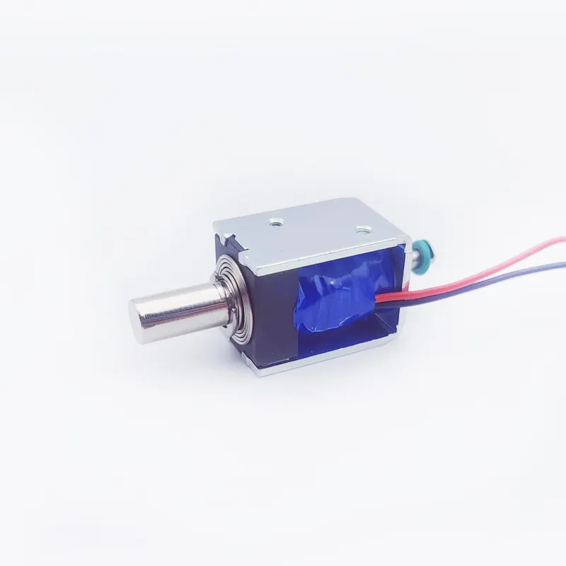
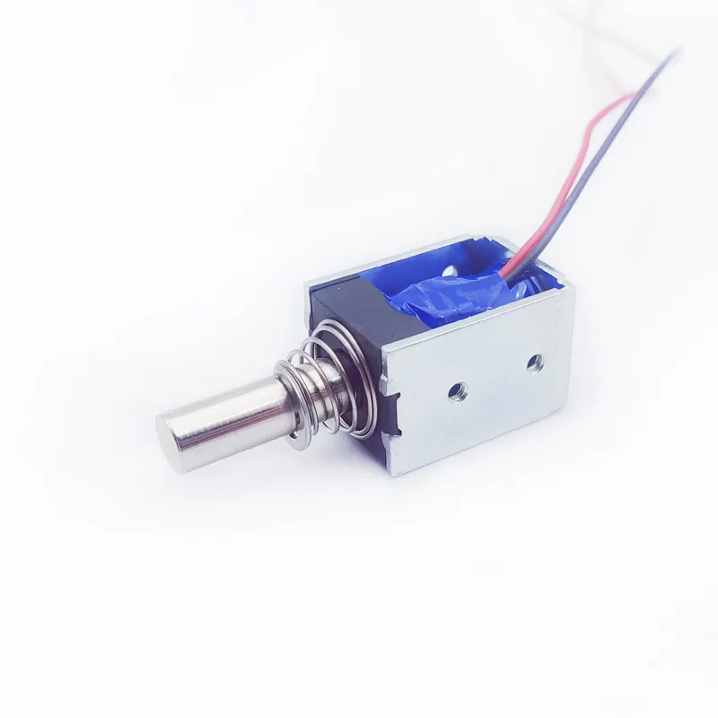
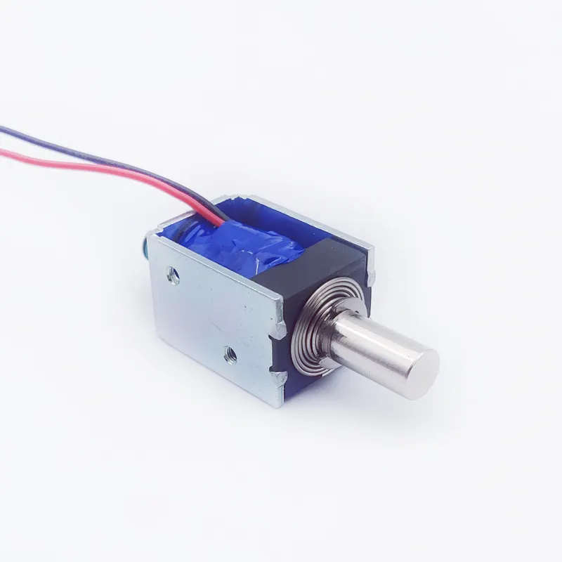
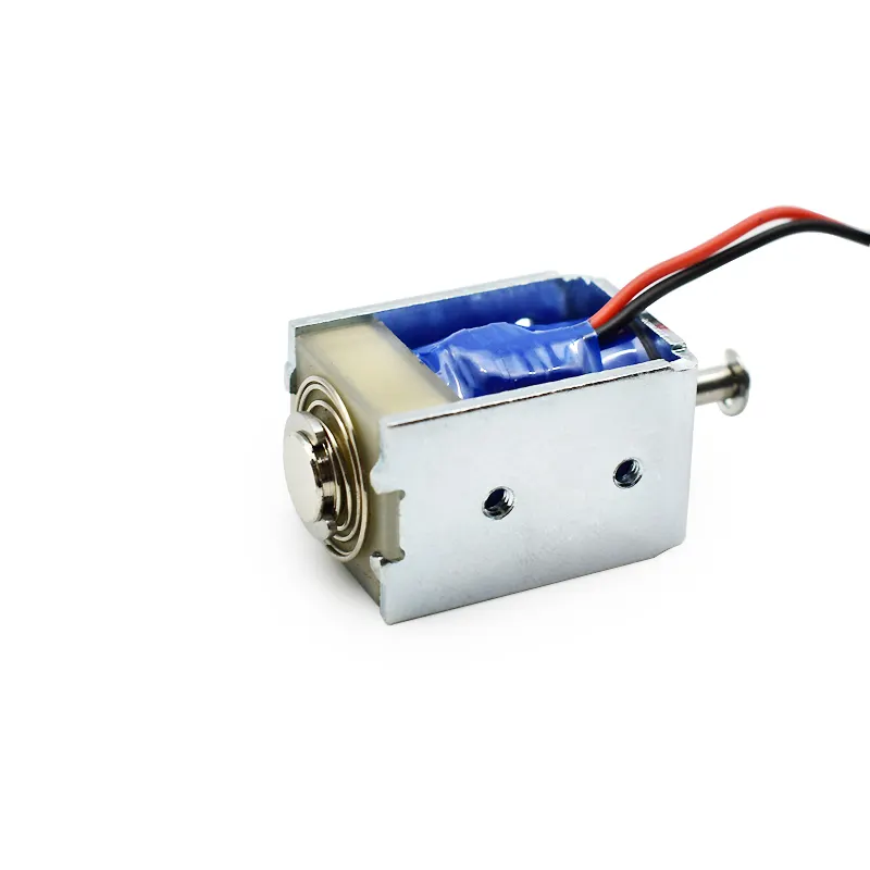
5. Bistable Solenoid Coil Optimization: Balancing Current, Turns, and Pulse Duration
The coil determines the controllable electromagnetic field used to switch the Bistable Solenoid. Its design must match the magnetic circuit and the required force-stroke performance.
The magnetomotive force is commonly represented by:NI
where (N) is the number of coil turns and (I) is the current. Increasing either value can increase magnetomotive force, but the practical result depends on resistance, inductance, magnetic saturation, available voltage, and pulse duration.
A coil with more turns is not automatically better. More turns can increase inductance and resistance, potentially slowing current rise or increasing copper resistance. A coil with fewer turns may allow higher current but require a driver capable of delivering that current safely.
For a voltage-driven coil, current does not necessarily reach its steady-state value immediately. The coil’s inductance affects the current-rise profile. If the switching pulse is too short, the current may not reach the level needed to release the magnetic latch and complete the stroke.
The coil design process should therefore evaluate:
Rated voltage and voltage tolerance
Coil resistance at the reference temperature
Inductance
Peak current
Current-rise time
Pulse duration
Copper wire diameter
Winding space and fill factor
Insulation requirements
Switching frequency and thermal rise
A practical solution is to measure the actual current waveform during switching and compare it with the force-stroke requirement. This helps distinguish an electromagnetic design limitation from a control-circuit limitation.
For example, if the coil current rises too slowly, changing the pulse duration or driver strategy may improve switching. If the current reaches its intended level but the plunger still fails to move, the magnetic circuit, holding force, friction, or spring load may require modification.
6. Bistable Solenoid Permanent Magnet Optimization: Holding Force Without Excessive Release Force
The permanent magnet creates the magnetic holding force that allows many Bistable Solenoid designs to retain their positions without continuous coil energization. However, stronger magnetic holding force is not always desirable.
If the magnet produces excessive holding force, the coil may require a stronger pulse to release the plunger. This can increase peak current, electrical energy, driver complexity, and thermal stress. If the magnet is too weak, the actuator may not remain stable under external loads, shock, or vibration.
The design objective is to establish an appropriate balance between holding force and release capability.
Important permanent-magnet design variables include:
Magnet material and grade
Magnet dimensions
Magnetization direction
Position within the magnetic circuit
Operating temperature
Magnetic working point
Pole geometry and air gap
Required holding force at each stable position
The magnet should be selected based on the complete magnetic circuit, not simply its nominal material grade or surface field value.
For applications exposed to elevated temperatures, the temperature characteristics of the permanent magnet must also be considered. Magnetic properties can vary with temperature, and some materials have greater resistance to irreversible demagnetization than others.
A reliable Bistable Solenoid design should verify holding force and switching force across the specified temperature range. This prevents a design from performing well at room temperature but becoming difficult to release or insufficiently stable under real operating conditions.
7. Bistable Solenoid Plunger Geometry: Improving Force and Motion Accuracy
The plunger is both a moving mechanical component and part of the magnetic circuit. Its dimensions and surface characteristics directly influence magnetic force, friction, alignment, and stroke repeatability.
For precision applications, plunger design should consider more than nominal diameter and length.
Plunger diameter and pole area: These influence the effective magnetic area and flux distribution. Increasing diameter may improve magnetic cross-section, but it also changes moving mass, package size, and guide requirements.
Plunger length: The length affects the magnetic path, mechanical guidance, and available stroke. An unsuitable length can produce excessive overhang or inadequate support.
Pole-face shape: The geometry at the magnetic interface affects the air-gap distribution and force characteristics. Small changes to pole geometry may help adjust starting force or end-position holding force.
Surface finish: Rough surfaces can increase friction and wear. Appropriate machining and finishing processes help achieve consistent movement.
Concentricity and straightness: Misalignment between the plunger and guide can create side loading, uneven contact, and inconsistent friction.
One effective solution is to optimize plunger geometry together with the guide and pole-piece geometry. Treating these parts separately can lead to a design that performs well magnetically but experiences mechanical binding.
For an OEM Bistable Solenoid, the target should be a plunger that provides the required magnetic performance while moving smoothly within the specified tolerance range.
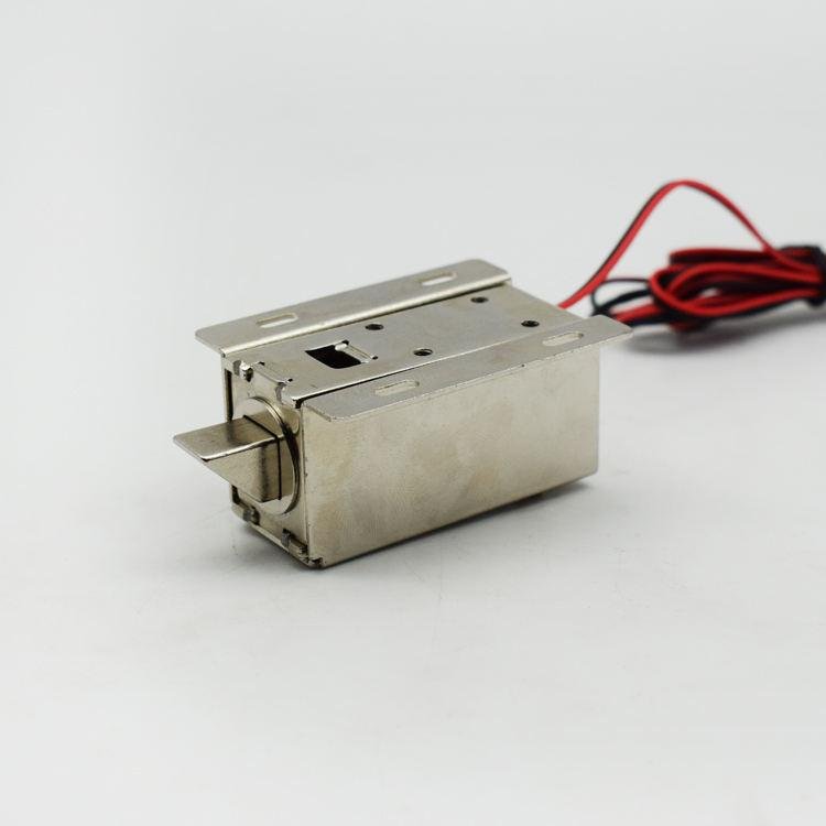
8. Bistable Solenoid Spring Matching: Controlling Net Force Across the Stroke
Spring selection is a major part of force-stroke optimization whenever the actuator architecture uses a spring.
A compression spring typically produces a force that increases with compression. For an ideal linear spring, the relationship can be represented by Hooke’s law:[ F_s = kx]
where (F_s) is spring force, (k) is the spring rate, and (x) is the spring deflection from its reference condition.
In a real Bistable Solenoid, spring force must be considered alongside magnetic force, friction, and external load.
An overly strong spring can prevent the plunger from reaching its destination. An overly weak spring may not provide the required return assistance, preload, or mechanical stability.
Spring matching should consider:
Spring rate
Initial preload
Free length
Installed length
Working compression
Maximum compression
Fatigue performance
Temperature and material characteristics
The most effective approach is to compare the spring-force curve with the available electromagnetic force over the complete stroke.
For example, if the actuator has adequate force at the beginning but insufficient net force near the middle of travel, the spring rate or preload may be too high for that region. Alternatively, the magnetic circuit may need to be reshaped to provide more force where it is needed.
Spring optimization is therefore not simply a process of selecting a standard spring with the correct nominal force. It is a matching exercise between mechanical resistance and the position-dependent force of the Bistable Solenoid.
9. Bistable Solenoid Stroke Control: Achieving the Required Travel and End Position
Stroke is the linear displacement of the plunger between its defined mechanical positions. In a Bistable Solenoid, the required stroke must be sufficient to operate the customer’s mechanism while remaining compatible with the actuator’s available force and magnetic geometry.
Increasing stroke can make the magnetic design more challenging because the plunger may need to move through a larger range of magnetic conditions. A design that works reliably with a short stroke may not maintain adequate force after the stroke is extended.
The key is to define the actual mechanical travel required by the application before finalizing the actuator dimensions.
Engineers should establish:
Required minimum and maximum stroke.
The mechanical load at different positions.
Whether the load changes during movement.
Required end-position accuracy.
Permissible mechanical impact.
Whether the actuator needs a physical stop.
Allowable overtravel or clearance.
A mechanical stop can help define the final position, but the stop should not be used to compensate for an inadequate magnetic design. Excessive impact against a stop can cause noise, wear, deformation, or inconsistent positioning.
For applications requiring repeatable output positioning, the actuator’s end position should be designed around the customer’s complete mechanism. The manufacturer’s plunger stroke and the customer’s required functional travel are related but not necessarily identical.
10. Bistable Solenoid Friction and Mechanical Resistance: Eliminating Hidden Force Losses
A Bistable Solenoid can have sufficient theoretical electromagnetic force and still fail in actual operation because of friction.
Friction is often underestimated during initial design. In a compact actuator, small changes in guide clearance, surface finish, alignment, contamination, or lubrication can significantly influence the available net force.
Common sources of friction include:
Plunger-to-guide contact
Misaligned housing components
Burrs or machining defects
Surface roughness
Excessive side loading
Inconsistent assembly
Contamination or foreign particles
Changes in lubricant behavior
The first solution is to establish an appropriate guide-clearance range. Excessively tight clearance can increase contact resistance, while excessive clearance can allow plunger tilt and unstable movement.
The second solution is to control surface quality. The plunger and guide should have suitable material combinations and surface finishes for the application.
The third solution is to control assembly alignment. A plunger that moves smoothly before final assembly may experience binding after the housing, coil, and mounting components are installed.
A useful validation method is to measure mechanical movement resistance separately from electromagnetic force. This helps engineers identify whether poor switching is caused by insufficient magnetic force or excessive mechanical friction.
For a precision Bistable Solenoid, reducing unnecessary friction can be more effective than simply increasing coil power.

11. Bistable Solenoid Force-Stroke Testing: How to Measure and Validate Performance
Simulation and theoretical calculations are valuable during development, but actual testing is necessary to verify the force-stroke behavior of a manufactured actuator.
A typical force-stroke test uses a controlled displacement fixture and a calibrated force sensor. The plunger is moved through its defined stroke while force is recorded at multiple displacement points.
The test should clearly identify what is being measured.
Possible measurements include:
Electromagnetic force under a defined current
Holding force at each stable position
Release force
Spring force
Mechanical resistance
Net output force
Force during extension or retraction
These values should not be mixed into one curve without clear labeling.
For a Bistable Solenoid, testing should also record the electrical conditions. A force measurement without the corresponding coil current, voltage, pulse duration, and plunger position may be difficult to reproduce or interpret.
A practical test plan should define:
Test Parameter | What Should Be Recorded |
|---|---|
Accident vasculaire cérébral | Actual displacement range |
Forcer | Force at defined positions |
Tension | Applied coil voltage |
Actuel | Peak and time-dependent current |
Pulse duration | Energization time |
Temperature | Ambient and, where relevant, coil temperature |
Direction | Switching direction |
Stable position | Holding behavior after the pulse |
Repeatability | Variation across repeated cycles |
Testing should be performed in both switching directions because the two directions may not have identical force characteristics. The results should also be checked against the actual customer load rather than only under an unloaded bench condition.
12. Bistable Solenoid Precision Control: Using Pulse Parameters to Improve Switching
The electrical pulse is the control input that initiates movement. Its characteristics can strongly influence switching reliability and response time.
Three parameters are particularly important:
Voltage: The applied voltage influences the rate at which coil current rises and the current level available during the pulse. Supply-voltage variation must be included in the design evaluation.
Pulse duration: The pulse must last long enough for the coil to generate the required magnetic field and for the plunger to complete the necessary movement. A pulse that is too short may result in incomplete switching.
Polarity: Some single-coil permanent-magnet Bistable Solenoids use opposite current directions to switch between positions. Other designs may use different electrical arrangements. The driver must match the actual actuator architecture.
A common engineering mistake is to increase pulse duration whenever switching becomes unreliable. This may temporarily improve performance, but it does not necessarily solve the underlying problem.
If the actuator has excessive friction or an inadequate force margin, a longer pulse may only increase heating and energy consumption.
A better approach is to examine the coil-current waveform and the mechanical response together. Engineers can then determine whether the problem comes from current rise, insufficient magnetic force, mechanical resistance, or an unsuitable pulse profile.
For OEM products, the final pulse parameters should be validated using the intended driver circuit, actual supply conditions, and real mechanical load.
13. Bistable Solenoid Temperature and Operating Conditions: Maintaining Force Consistency
A force-stroke curve measured at room temperature does not automatically represent actuator performance under every operating condition. Temperature can influence coil resistance, permanent-magnet characteristics, spring behavior, material dimensions, lubricant performance, and mechanical friction.
For example, copper resistance increases as coil temperature rises. In a voltage-driven system, higher resistance generally reduces current, which may reduce the electromagnetic force available during switching.
Permanent magnets also have temperature-dependent magnetic properties. The magnitude and reversibility of these changes depend on the magnet material and operating conditions.
Mechanical components can also change with temperature. Differences in thermal expansion between the plunger, guide, and housing may alter clearances. Lubricant viscosity can change, potentially affecting movement resistance.
Un fiable Bistable Solenoid should therefore be validated across its specified operating-temperature range.
Temperature-related factor | Potential influence | Engineering solution |
|---|---|---|
Coil resistance | Changes pulse current | Validate current at temperature limits |
Permanent magnet | Changes magnetic holding characteristics | Select an appropriate magnet material |
Guide clearance | Changes with thermal expansion | Evaluate material combinations and tolerances |
Spring | Changes in mechanical characteristics | Select suitable spring material |
Lubrication | Changes friction behavior | Validate lubricant for the environment |
Housing | Influences heat transfer and dimensional stability | Optimize housing material and structure |
For applications with frequent switching, thermal testing should also consider operating frequency and pulse energy. A Bistable Solenoid may not require continuous holding current, but repeated switching can still create significant average heating.

14. Custom Bistable Solenoid Manufacturer: Engineering Solutions for Production Consistency
Developing an accurate force-stroke curve is only part of the challenge. The design must also be manufactured consistently. A prototype may achieve excellent performance, but mass production introduces variations in coil winding, magnet strength, machining dimensions, spring characteristics, surface treatment, and assembly position.
These variations can change the force-stroke curve and reduce the available switching margin.
This is where the capabilities of a professional custom Bistable Solenoid manufacturer become important.
SF is a customized electromagnet manufacturer with more than 10 years of manufacturing experience. We have an experienced engineering team and a 6,000 m² factory to support customized electromagnetic product development and manufacturing. We have helped many brand customers customize different types of electromagnets, with products exported to more than 60 countries and regions.
For Bistable Solenoid development, our engineering approach focuses on matching the actuator’s electromagnetic characteristics with the customer’s mechanical and electrical requirements.
The design and manufacturing evaluation can include:
Magnetic circuit optimization: Evaluate pole geometry, magnetic materials, air gaps, flux paths, and permanent-magnet characteristics to achieve the required force profile.
Coil customization: Select winding parameters according to voltage, current, pulse duration, available space, and thermal requirements.
Plunger and guide design: Optimize dimensions, surface finish, clearance, alignment, and mechanical interfaces to reduce friction and improve motion consistency.
Spring matching: Select spring rate and preload according to the required force balance throughout the stroke.
Housing and assembly design: Control component positioning and mechanical relationships that influence magnetic and mechanical performance.
Performance validation: Evaluate force, stroke, switching behavior, and other agreed requirements under defined test conditions.
For OEM customers, the objective is not simply to produce a solenoid that meets one laboratory measurement. It is to develop a Bistable Solenoid that can perform reliably in the customer’s actual product and remain within the agreed specifications during production.
15. Bistable Solenoid Design Checklist: How to Specify Force and Stroke Requirements
Before requesting a quotation or prototype from a Bistable Solenoid factory, OEM engineers should prepare a clear application specification.
A detailed specification helps the manufacturer identify the correct magnetic architecture and avoid unnecessary redesign during development.
The following checklist provides a practical starting point.
Design area | Information to provide | Why it matters |
|---|---|---|
Stable positions | Required Position A and Position B | Defines bistable behavior |
Accident vasculaire cérébral | Required travel in mm | Establishes mechanical movement |
Starting force | Minimum force needed to initiate motion | Determines release capability |
Working force | Required force during movement | Determines stroke reliability |
Holding force | Required retention force at each position | Determines magnetic stability |
External load | Load profile throughout the stroke | Defines actual operating resistance |
Coil voltage | Nominal and allowable voltage range | Determines electrical design |
Pulse duration | Required or available pulse time | Influences switching performance |
Actuel | Maximum available driver current | Determines coil compatibility |
Switching frequency | Expected cycles per unit time | Influences thermal design |
Temperature | Minimum and maximum operating temperature | Defines environmental limits |
Lifetime | Required switching cycles | Influences mechanical and material design |
Installation | Mounting dimensions and orientation | Ensures product integration |
Power-loss behavior | Required state when power is removed | Determines the actuator architecture |
The most important information is the actual load profile.
For example, a mechanism may require 5 N at the beginning of the stroke, 8 N in the middle, and 3 N at the end. These are illustrative values, not universal Bistable Solenoid specifications. They demonstrate why one maximum-force figure cannot fully describe an actuator’s suitability.
A manufacturer should compare the required load curve with the available actuator force curve, accounting for spring force, friction, tolerances, and operating conditions.
The design should then be validated with the customer’s actual mechanical assembly whenever possible.
Frequently Asked Questions About Bistable Solenoid Force-Stroke Curves
What is a force-stroke curve in a Bistable Solenoid?
A force-stroke curve shows how the force of a Bistable Solenoid changes as its plunger moves through its travel. It helps engineers evaluate starting force, working force, holding force, and the actuator’s ability to complete the required movement.
Why is starting force important?
Starting force determines whether the actuator can release its initial stable position and begin moving. A Bistable Solenoid may have sufficient end-position holding force but still fail to switch if the initial electromagnetic force cannot overcome magnetic retention, spring force, friction, and external load.
How can I increase the force of a Bistable Solenoid?
Potential solutions include optimizing the magnetic circuit, adjusting coil turns and current, modifying pole geometry, reducing unnecessary air gaps, selecting appropriate magnetic materials, and improving the plunger design. Increasing coil power is only one option and may introduce thermal or electrical limitations.
Does a stronger permanent magnet always improve Bistable Solenoid performance?
No. A stronger permanent magnet may improve holding force, but it can also increase the force or energy needed to release the existing magnetic latch. Magnet strength must be matched to the coil and magnetic circuit.
How does spring force affect the Bistable Solenoid force-stroke curve?
Spring force changes with displacement and contributes to the total mechanical resistance or assistance. An incorrectly selected spring rate or preload can prevent switching or create inconsistent movement.
Why does a Bistable Solenoid work during testing but fail in the final product?
Possible causes include differences in external load, mounting alignment, guide clearance, friction, supply voltage, pulse duration, temperature, and assembly tolerances. The actuator should be validated under the actual application conditions rather than only in an unloaded bench test.
How can a manufacturer improve force-stroke consistency in mass production?
A manufacturer should control critical component dimensions, coil electrical characteristics, magnet specifications, spring force, surface finish, assembly alignment, and test conditions. Statistical process control and suitable measurement methods can help monitor variation across production batches.
Can a custom Bistable Solenoid manufacturer adjust the force and stroke?
Yes. Depending on the required performance and available package space, the manufacturer can customize the magnetic circuit, coil, permanent magnet, plunger, spring, guide, housing, and electrical interface to achieve the target force-stroke characteristics.
Force-Stroke Optimization Is the Key to Precision Bistable Solenoid Control
The force-stroke curve is one of the most important engineering tools for developing a reliable Bistable Solenoid. It shows whether the actuator can generate sufficient force to release its initial magnetic latch, move through the required stroke, overcome spring and friction resistance, and establish a stable final position.
Achieving the correct force-stroke characteristics requires more than increasing coil power. It involves coordinated engineering across the entire actuator.
The most important solutions include:
Magnetic circuit optimization to control flux distribution, air-gap reluctance, and magnetic saturation.
Coil optimization to achieve the required current and magnetic field within the available pulse duration.
Permanent magnet selection to balance holding force and release capability.
Plunger geometry optimization to improve magnetic performance and mechanical movement.
Spring matching to maintain an appropriate force balance throughout the stroke.
Friction reduction through better surface finish, guide clearance, alignment, and assembly control.
Pulse optimization to ensure reliable switching without unnecessary energy consumption or heating.
Force-stroke testing to verify actual performance under defined electrical, mechanical, and environmental conditions.
Manufacturing process control to maintain performance consistency from prototype to mass production.
For OEM customers, the most effective solution is to work with a manufacturer that understands both electromagnetic design and practical manufacturing requirements.
SF brings more than 10 years of customized electromagnet manufacturing experience, an experienced engineering team, a 6,000 m² factory, and experience serving brand customers in more than 60 countries and regions.
Whether your application requires a compact battery-powered actuator, a smart locking mechanism, an industrial switching device, a precision valve actuator, or another customized electromagnetic solution, SF can support the development of a Bistable Solenoid around your specified force, stroke, voltage, pulse, and installation requirements.
The best Bistable Solenoid is not necessarily the actuator with the highest peak force. It is the actuator that delivers the right force at the right position, throughout the required stroke, under real operating conditions—and maintains that performance consistently in production.
If you are looking for a custom Bistable Solenoid manufacturer, a reliable Bistable Solenoid factory, or an experienced China Bistable Solenoid manufacturer, SF welcomes your drawings, technical specifications, and application requirements for engineering evaluation.
Fabrication sur mesure de tous types d'électroaimants, contactez l'usine d'électroaimants SF WhatsApp +86 189 0261 1680