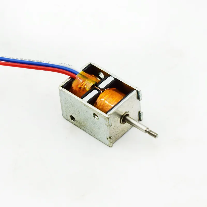


1. Why Hold Force and Pulse Width Matter in a Bistable Solenoid
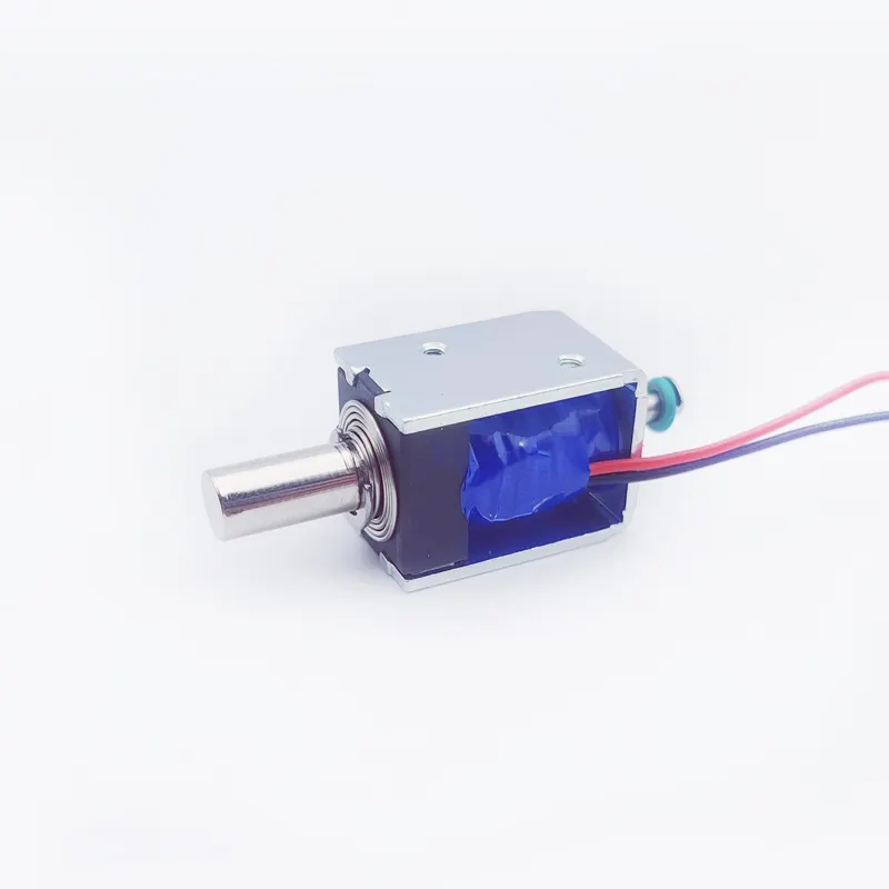
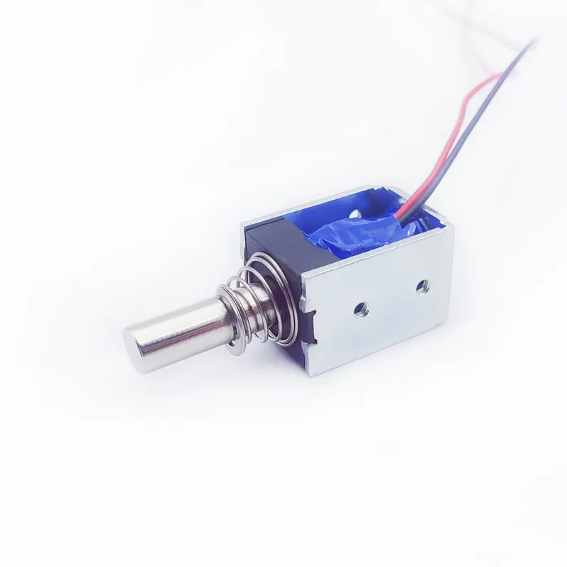
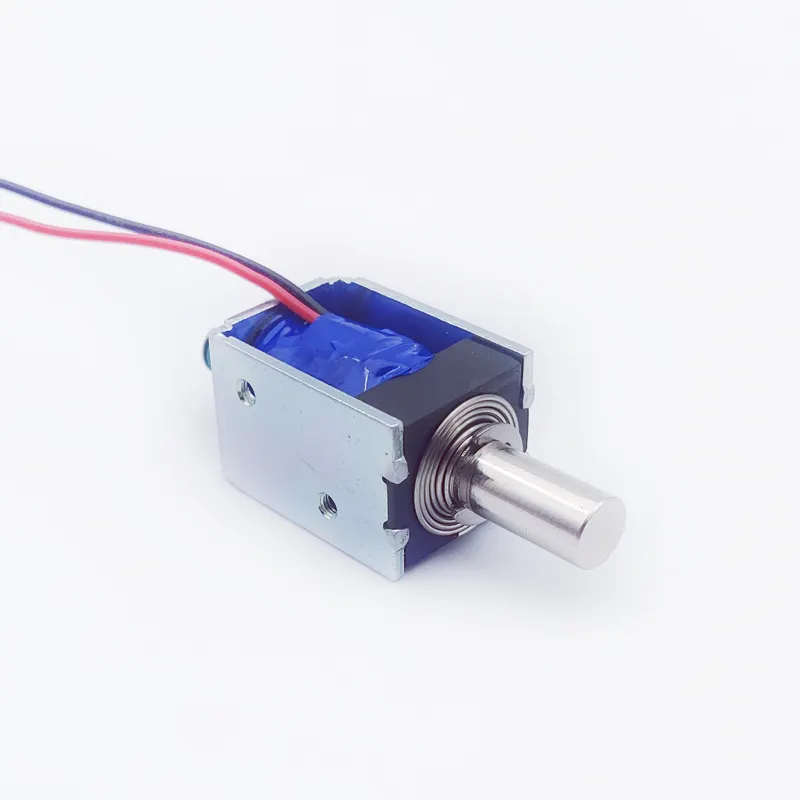
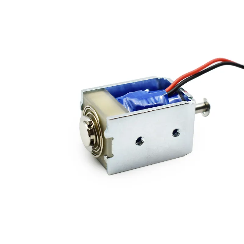
A Bistable Solenoid is designed to maintain two stable mechanical positions without requiring continuous electrical power. This characteristic makes it an attractive actuator solution for battery-powered equipment, smart locks, industrial automation systems, medical devices, automotive components, and other applications where energy efficiency and reliable switching are essential.
However, achieving optimum bistable performance requires more than simply selecting a powerful permanent magnet or applying a short electrical pulse. Two parameters are particularly important: hold force and pulse width.
Hold force determines whether the plunger can remain securely in its intended position under external loads, vibration, shock, and other operating conditions. Pulse width determines how long electrical energy must be applied to move the plunger reliably from one stable position to the other.
If the holding force is insufficient, the actuator may release unexpectedly. If the holding force is excessive, the switching pulse may not generate enough force to overcome the magnetic attraction and mechanical resistance. Similarly, an excessively short pulse can cause incomplete switching, while an unnecessarily long pulse increases energy consumption and coil heating.
For engineers developing a custom Bistable Solenoid, the objective is to establish an appropriate balance between magnetic holding performance, switching force, pulse energy, mechanical resistance, and thermal limits.
This guide explains how to calculate and optimize hold force and pulse width, how these parameters interact, and how a professional Bistable Solenoid manufacturer can help customers develop reliable actuator solutions.
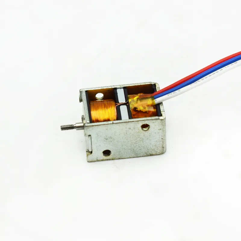
2. Understanding Hold Force in a Bistable Solenoid
Hold force is the mechanical force required to maintain the plunger in a stable position against an opposing load.
In a permanent-magnet-based Bistable Solenoid, magnetic attraction commonly provides the holding force at one or both end positions. The permanent magnet maintains the magnetic circuit after the switching pulse has ended, allowing the actuator to retain its position without continuous coil energization.
Unlike a conventional monostable solenoid, which typically relies on a spring to return the plunger to its default position when power is removed, a bistable design has two mechanically stable states.
The holding mechanism can vary according to the magnetic architecture:
Permanent-magnet latching: A permanent magnet provides magnetic retention at an end position.
Dual-position magnetic latching: Magnetic structures provide stable retention at both end positions.
Magnetic and spring-assisted latching: Magnetic attraction stabilizes one position while a spring or another mechanical element contributes to stability at the opposite position.
Therefore, engineers should not assume that every bistable actuator has identical holding force in both directions.
A complete specification should identify:
Holding force at Position A.
Holding force at Position B.
Minimum acceptable holding force.
Maximum acceptable release force.
External load direction and magnitude.
Required resistance to vibration and shock.
Operating temperature range.
The most important principle is that holding force must be evaluated at the actual stable positions and under the application’s real mechanical conditions. A single maximum-force value cannot fully describe bistable performance.
3. Bistable Solenoid Hold Force: The Main Factors That Determine Magnetic Retention
The holding force of a Bistable Solenoid is determined by several interacting magnetic and mechanical parameters. Increasing one parameter does not always improve overall performance because magnetic retention and switching capability must be optimized together.
The major factors include:
1. Permanent magnet strength
The permanent magnet establishes the magnetic field responsible for maintaining the plunger in its stable position. Magnet grade, dimensions, magnetic properties, and operating temperature all influence the available holding force.
2. Magnetic air gap
The air gap between the plunger and magnetic pole structure is particularly important. Even a relatively small change in the effective air gap can significantly affect magnetic reluctance and force.
3. Magnetic circuit geometry
The dimensions and configuration of the yoke, pole pieces, plunger, and magnet determine how effectively magnetic flux is concentrated through the working region.
4. Plunger material
Magnetic permeability, saturation characteristics, and material consistency influence the magnetic circuit. The selected material must be appropriate for the required force and response characteristics.
5. Contact surface and mechanical alignment
Surface flatness, contact geometry, concentricity, and assembly tolerances affect the effective magnetic gap and the repeatability of the holding force.
6. External mechanical load
The actual retention requirement depends on the force exerted by connected components, springs, seals, linkages, and the operating environment.
For this reason, a professional Bistable Solenoid factory should evaluate the complete magnetic and mechanical assembly rather than selecting a permanent magnet based only on its nominal magnetic strength.
4. How to Calculate the Required Hold Force for a Bistable Solenoid
The first step in designing a reliable Bistable Solenoid is calculating the minimum holding force required by the application.
The basic engineering approach is to identify all external forces that may move the plunger away from its stable position and then establish an appropriate safety margin.
A simplified design relationship is: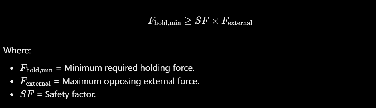
Spring preload or spring reaction.
Gravity acting on the moving assembly.
Mechanical linkage resistance.
Pressure or fluid forces.
Vibration-induced inertial force.
Shock-induced inertial force.
Forces transmitted from connected components.
Example: Calculating the required holding force
Assume a bistable actuator is used in a mechanical locking device.
The estimated opposing forces are:
Force source | Estimated force |
|---|---|
External mechanical load | 8 N |
Spring reaction | 3 N |
Gravity component | 1 N |
Total static opposing force | 12 N |
If the design uses a safety factor of 1.5:
The actuator should therefore provide at least 18 N of holding force under the specified design conditions.
This is an illustrative calculation, not a universal safety factor. The appropriate margin depends on load uncertainty, temperature, vibration, shock, manufacturing tolerances, and the consequences of unintended release.
For shock-sensitive applications, engineers should calculate inertial loading separately rather than assuming that a static safety factor automatically covers dynamic events.
The final requirement should also specify whether the force is measured at the actual contact position, under a defined fixture configuration, and at a specified temperature.
5. Calculating Magnetic Holding Force: Understanding the Magnetic Circuit
For a simplified magnetic circuit with a dominant air gap, magnetic holding force can be approximated using the Maxwell stress relationship:
Where:
\(F\) = Approximate magnetic force in newtons.
\(B\) = Magnetic flux density in the effective air gap, in teslas.
\(A\) = Effective pole-face area in square meters.
\(\mu_0\) = Permeability of free space, approximately \(4\pi\times10^{-7}\,H/m\).
This equation provides a useful first-order estimate. It assumes a reasonably uniform magnetic field across the effective pole area and does not fully account for leakage flux, fringing, nonuniform contact, saturation, or complex three-dimensional magnetic geometry.
Example: Estimating magnetic holding force
Suppose the effective pole area is:
The estimated flux density at the working interface is:
Substituting these values:
The approximate force is:
This result indicates the theoretical magnetic force under the simplified assumptions.
However, it does not establish that the manufactured actuator will deliver exactly 14.3 N. Real-world holding force depends on the complete magnetic circuit, effective air gap, contact conditions, material properties, and assembly tolerances.
For an accurate custom Bistable Solenoid, magnetic simulation and physical force testing should be used together.
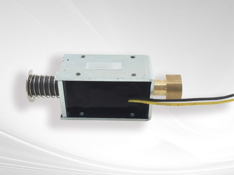
6. How Air Gap and Pole Geometry Influence Bistable Solenoid Hold Force
Air gap control is one of the most important factors in achieving consistent holding force.
Magnetic reluctance increases with air-gap length. When the effective air gap becomes larger, less magnetic flux may pass through the intended working path for a given magnetic source.
This means that small dimensional variations can create measurable differences in holding force.
Several manufacturing details require attention:
Plunger end-face flatness.
Pole-face flatness.
Surface roughness.
Plunger concentricity.
Assembly alignment.
Contact clearance.
Coating or plating thickness.
Mechanical stops and end-position repeatability.
For example, if a design relies on close contact between the plunger and a pole face, excessive coating thickness or an uneven contact surface may create an unintended residual gap.
This can reduce magnetic retention even when the permanent magnet itself meets its material specification.
Pole geometry also matters. Increasing pole-face area may improve the theoretical force capability, but only when the magnetic flux can be distributed effectively through that area. A larger pole face does not automatically produce a proportional increase in holding force.
The magnetic circuit must also avoid excessive saturation in the pole pieces, yoke, and plunger.
A capable Bistable Solenoid manufacturer should therefore optimize the pole geometry, magnetic materials, air gap, and assembly tolerances as one integrated design problem.
7. Understanding the Relationship Between Hold Force and Switching Force
One of the most common design mistakes in bistable actuators is maximizing holding force without evaluating the force required to release the plunger.
A strong magnetic holding force can prevent unwanted movement, but it also creates a magnetic resistance that the switching pulse must overcome.
The actuator must satisfy two different requirements:
It must remain stable when no switching pulse is applied.
It must switch reliably when the appropriate pulse is applied.
A simplified force balance during switching can be expressed as:
Where:
\(F_{\text{coil}}\) = Electromagnetic force generated by the energized coil.
\(F_{\text{other}}\) = Other force contributions, such as a spring, depending on direction.
\(F_{\text{resistance}}\) = Opposing forces, including magnetic retention, friction, and external load.
\(x\) = Plunger position.
\(t\) = Time.
The sign and contribution of each force depend on the actuator architecture and switching direction.
For successful switching, the available driving force must overcome the opposing forces throughout the necessary movement.
It is not enough for the coil to generate a high peak force at one point in the stroke. The force must remain sufficient at the critical positions where the plunger could otherwise stall.
This is why engineers should analyze the complete force-stroke curve rather than relying on a single rated force value.
8. How to Calculate Pulse Width for Optimum Bistable Solenoid Switching
Pulse width is the duration for which the coil is energized during a switching operation.
In a Bistable Solenoid, the pulse must provide enough electrical energy to establish the required magnetic field and move the plunger into the opposite stable position.
An excessively short pulse may fail to complete the movement. An excessively long pulse may waste energy, increase coil temperature, and reduce overall system efficiency.
There is no universal pulse width for all bistable solenoids. The appropriate value depends on coil resistance, inductance, supply voltage, magnetic circuit, moving mass, stroke, mechanical load, friction, and switching direction.
For an initial electrical estimate, a simplified RL circuit model can be used:
Where:
\(I(t)\) = Coil current at time \(t\).
\(V\) = Applied voltage.
\(R\) = Coil resistance.
\(L\) = Coil inductance.
\(t\) = Time after voltage is applied.
The electrical time constant is:
For a simplified fixed-inductance RL circuit, current reaches approximately:
63.2% of its final steady-state value after \(1\tau\).
86.5% after \(2\tau\).
95.0% after \(3\tau\).
98.2% after \(4\tau\).
However, a real solenoid does not always behave like a fixed-inductance RL circuit. Inductance changes with plunger position, magnetic saturation, and current. Motion also introduces electromechanical effects.
Therefore, this equation is useful for estimating current rise, but it cannot independently determine the correct switching pulse width.
9. A Practical Example: Estimating the Initial Pulse Width
Consider a hypothetical Bistable Solenoid with the following electrical parameters:
Parameter | Value |
|---|---|
Applied voltage | 12 V |
Coil resistance | 24 Ω |
Coil inductance | 48 mH |
Supply type | DC |
Required operation | Short switching pulse |
The electrical time constant is:
The theoretical steady-state current under the simplified fixed-inductance model is:
The approximate current after different time intervals is:
Time | Actuel | Percentage of steady-state current |
|---|---|---|
2 ms | 0.316 A | 63.2% |
4 ms | 0.432 A | 86.5% |
6 ms | 0.475 A | 95.0% |
8 ms | 0.491 A | 98.2% |
This table illustrates how quickly current approaches its theoretical steady-state value.
However, it would be incorrect to conclude that the optimum pulse width must be 6 ms or 8 ms.
The actual pulse must be determined by measuring when the plunger completes its movement and achieves stable retention.
For example, if testing shows that the plunger consistently reaches its target position before the end of a 6 ms pulse, the pulse may be shortened after validating switching reliability across the required operating conditions.
If the plunger moves slowly because of a high external load or insufficient current rise, a longer pulse or a different coil design may be necessary.
The final pulse width must be established through electrical and mechanical testing, not by the RL equation alone.
10. How Coil Resistance, Inductance, and Voltage Affect Pulse Width
The coil is the electrical energy source of a bistable actuator. Its characteristics directly influence how quickly the magnetic field develops and how much energy is delivered during switching.
Three parameters deserve particular attention.
Coil resistance
Coil resistance determines the steady-state current under a given voltage. Higher resistance generally reduces current in a voltage-driven circuit.
However, simply reducing resistance is not always the best solution. A lower-resistance coil may draw more current, increasing driver requirements and thermal stress.
Coil inductance
Inductance controls the rate of current rise. A coil with higher inductance may require more time to reach a given current under the same voltage and resistance.
The actual inductance of a solenoid can vary with plunger position and magnetic conditions.
Supply voltage
Higher applied voltage can increase current rise speed, potentially reducing the pulse duration required to reach a target current.
However, higher voltage also increases electrical and insulation stress. Driver ratings, switching transients, coil temperature, and component protection must all be considered.
For a custom Bistable Solenoid, coil optimization should consider:
Number of winding turns.
Wire diameter.
Coil resistance.
Inductance across the stroke.
Rated voltage and voltage tolerance.
Maximum switching current.
Pulse duration.
Switching frequency.
Thermal limits.
Driver circuit characteristics.
The objective is to develop a coil that generates sufficient switching force without exceeding the electrical and thermal limits of the application.
11. Calculating Pulse Energy and Managing Coil Temperature
Although a bistable actuator does not normally require continuous holding current, every switching event consumes electrical energy.
The energy delivered to the coil during a pulse can be calculated from:
Where:
\(E\) = Electrical energy delivered during the pulse.
\(V(t)\) = Instantaneous coil voltage.
\(I(t)\) = Instantaneous coil current.
\(t_p\) = Pulse duration.
For a simplified constant-voltage and constant-resistance approximation:
This approximation is useful when current is reasonably stable during the selected interval. For a rapidly rising current, the integral of instantaneous resistive loss provides a more accurate estimate.
The coil’s average power consumption depends on switching frequency.
If each switching event consumes energy \(E_p\), and the actuator performs \(f\) switching events per second:
For example, if a switching pulse consumes 0.1 J and the actuator performs one switching event every five seconds:
This is the average electrical energy consumption associated with switching, excluding driver losses and other system power requirements.
The practical advantage of a Bistable Solenoid is that it can retain its state without continuous holding current. However, frequent switching may still produce significant cumulative heating.
Engineers should evaluate:
Pulse energy.
Switching frequency.
Coil temperature rise.
Ambient temperature.
Heat dissipation through the housing.
Insulation temperature rating.
Repeated-operation conditions.
A pulse width that works during occasional bench testing may not be appropriate for a high-frequency industrial application.
12. Optimizing Hold Force and Pulse Width Together: A Design Comparison
Hold force and pulse width should never be optimized independently.
Increasing permanent-magnet strength may improve retention, but it may also increase the energy required to release the plunger. Increasing coil current may improve switching performance, but it may also increase power consumption and thermal stress.
The design objective is to establish a balanced operating window.
Design parameter | Too low | Too high | Optimization objective |
|---|---|---|---|
Magnetic holding force | Unintended release | Difficult switching | Reliable retention with manageable release force |
Coil current | Insufficient switching force | Excessive heating and driver stress | Adequate force within electrical limits |
Pulse width | Incomplete movement | Unnecessary energy consumption | Reliable switching with minimum validated duration |
Air gap | May create excessive attraction or mechanical interference, depending on geometry | Reduced magnetic force | Controlled magnetic and mechanical clearance |
Spring force | Inadequate mechanical assistance or return behavior | Excessive opposing load | Match the spring to the magnetic force profile |
Switching frequency | May not meet application requirements | Increased thermal accumulation | Match actual operating duty |
A good design process begins with the required holding force, then evaluates the release force and switching force profile.
The coil and pulse parameters are subsequently optimized to provide enough force and movement time under the worst-case operating conditions.
For some applications, it may be beneficial to use different pulse parameters for the two switching directions because the magnetic and mechanical resistance may not be symmetrical.
This is particularly important when the actuator uses different magnetic retention conditions at Position A and Position B.
13. Testing and Validation: How to Confirm the Correct Hold Force and Pulse Width
Engineering calculations provide a starting point, but actual testing is essential before releasing a custom Bistable Solenoid for mass production.
A professional validation program should cover both magnetic retention and switching performance.
Hold force testing
Measure the force required to pull the plunger away from each stable position.
The test should define:
Position A and Position B.
Pull direction.
Plunger contact condition.
Test fixture geometry.
Displacement rate.
Ambient and component temperature.
Minimum acceptable holding force.
Testing both positions is important because the holding force may differ depending on the magnetic architecture.
Pulse-width testing
Apply controlled switching pulses and record the electrical and mechanical response.
Useful measurements include:
Applied voltage waveform.
Coil current waveform.
Pulse duration.
Plunger displacement.
Switching time.
Successful arrival at the target position.
Final state retention.
A displacement sensor, high-speed data acquisition system, or other suitable instrumentation can help identify whether the plunger completes its stroke before the pulse ends.
Environmental and endurance testing
The actuator should also be evaluated under conditions representative of its intended application:
Minimum and maximum operating voltage.
Minimum and maximum ambient temperature.
Maximum external load.
Vibration and shock.
Repeated switching cycles.
Expected mounting orientation.
Mechanical tolerance variations.
The purpose is not simply to demonstrate that one prototype works. It is to establish a reliable operating window that can be maintained across production units.
14. How a Professional Bistable Solenoid Manufacturer Optimizes Custom Performance
Developing a high-performance Bistable Solenoid requires coordinated engineering across magnetic design, coil design, mechanical structure, manufacturing processes, and quality control.
This is why selecting an experienced custom Bistable Solenoid manufacturer is important, especially for applications with strict requirements for switching reliability, low power consumption, compact dimensions, or long-term retention.
SF is a professional custom electromagnet manufacturer with more than 10 years of manufacturing experience. Our engineering team works with brand customers to develop different types of customized electromagnets according to their application requirements.
Our 6,000 m² manufacturing facility provides a production base for customized electromagnet manufacturing, while our export experience covers more than 60 countries and regions.
For customers developing a custom bistable actuator, the engineering process should focus on several key areas.
1. Application requirement analysis
Before selecting a magnetic structure, engineers need to understand the actual application, including required holding force, stroke, external load, operating voltage, switching frequency, mounting orientation, and environmental conditions.
2. Magnetic circuit optimization
The permanent magnet, plunger, pole pieces, yoke, and air gap must work together. The objective is to achieve sufficient holding force without making switching unnecessarily difficult.
3. Coil and pulse optimization
Coil resistance, inductance, winding configuration, voltage, current, and pulse duration must be evaluated as a complete electrical system.
4. Mechanical structure optimization
Plunger dimensions, spring characteristics, guide clearance, contact geometry, and assembly tolerances all influence the final switching performance.
5. Prototype testing and design adjustment
Prototype testing should confirm actual holding force, release behavior, pulse response, and thermal performance. Design parameters can then be adjusted based on measured results.
6. Production consistency
A successful prototype must be translated into repeatable manufacturing specifications. Relevant inspection parameters may include coil resistance, key dimensions, magnet properties, spring characteristics, and force or switching performance.
As an experienced China Bistable Solenoid manufacturer, SF understands that different customers may require different combinations of holding force, switching energy, dimensions, and electrical characteristics. A standardized product is not always the best solution for a specialized application.
Our objective is to help customers develop electromagnet solutions that match their actual product requirements.

15. OEM Selection Checklist and Frequently Asked Questions About Bistable Solenoid Performance
Before choosing a Bistable Solenoid factory, buyers and engineering teams should prepare a clear technical specification. This helps reduce unnecessary design changes and makes prototype evaluation more efficient.
OEM Bistable Solenoid specification checklist
Specification | Information to provide |
|---|---|
Application | Smart lock, industrial equipment, automotive, medical device, etc. |
Operating principle | Permanent-magnet latching, dual-position latching, or other architecture |
Stable positions | Required number and mechanical definition of stable positions |
Holding force | Minimum force at Position A and Position B |
Accident vasculaire cérébral | Required plunger travel |
External load | Load magnitude and direction |
Tension nominale | Nominal and allowable voltage range |
Coil parameters | Resistance, inductance, or target current if known |
Pulse width | Initial target or allowable control range |
Switching frequency | Expected operations per unit time |
Operating temperature | Minimum and maximum temperature |
Mechanical dimensions | Maximum envelope and mounting requirements |
Lifetime | Required switching-cycle target |
Environmental conditions | Vibration, shock, humidity, dust, etc. |
Frequently Asked Questions aboud bistable solenoid
Q1: What is the difference between holding force and switching force in a Bistable Solenoid?
Holding force is the force that maintains the plunger in a stable position after the switching pulse ends. Switching force is the electromagnetic and mechanical driving force available to move the plunger from one stable position to the other.
A successful design must provide sufficient holding force without making the required switching force excessive.
Q2: How do I calculate the required holding force?
Start by calculating all external forces that may move the plunger away from its stable position. Include mechanical loads, spring forces, gravity, vibration, and shock where relevant. Apply an appropriate safety factor based on the application and verify the result through physical testing.
Q3: Can a stronger permanent magnet improve Bistable Solenoid performance?
A stronger permanent magnet may increase holding force, but it can also increase the force required to release the plunger. The correct magnet should be selected according to the complete magnetic circuit and switching requirements, rather than maximum magnetic strength alone.
Q4: How do I determine the correct pulse width?
Use coil resistance, inductance, and supply voltage to estimate current rise. Then test the actual actuator to identify the minimum pulse duration that consistently completes switching under the required voltage, load, temperature, and mechanical tolerance conditions.
Q5: Does a Bistable Solenoid consume power when holding its position?
A permanent-magnet-based bistable solenoid generally requires no continuous coil current to maintain its stable position. However, electrical energy is still required during switching. Driver electronics and other control components may also consume standby power.
Q6: Can the two switching directions use different pulse widths?
Yes. Different magnetic retention forces, spring contributions, and mechanical loads may create different switching requirements in each direction. The pulse width should be validated independently for both directions.
Q7: Why does a Bistable Solenoid work during prototype testing but fail in actual equipment?
Possible causes include higher external loads, assembly misalignment, insufficient voltage, increased friction, temperature variation, incorrect pulse duration, or changes in the effective magnetic air gap. Testing should reproduce the actual installation and operating conditions.
Q8: What should I provide when requesting a custom Bistable Solenoid?
Provide the required holding force, stroke, operating voltage, pulse-control method, external load, switching frequency, dimensions, temperature range, and application details. A professional manufacturer can use this information to evaluate the magnetic structure, coil, and mechanical design.
Achieving Reliable Bistable Performance Through Hold Force and Pulse Width Optimization
The performance of a Bistable Solenoid depends on the relationship between magnetic retention, switching force, coil characteristics, pulse duration, and mechanical resistance.
The required holding force should be calculated from the actual external load with an appropriate safety margin. Magnetic force estimation can provide an initial design reference, but air-gap control, pole geometry, material properties, and assembly tolerances must also be considered.
Pulse width should be estimated from the coil’s electrical characteristics and then validated through actual switching tests. The optimum pulse is not necessarily the longest pulse or the one that produces the highest current. It is the shortest validated pulse that reliably completes the required movement across the specified operating conditions while respecting electrical and thermal limits.
For OEM customers, working with an experienced manufacturer can make this optimization process more efficient. SF combines more than 10 years of customized electromagnet manufacturing experience, an experienced engineering team, a 6,000 m² factory, and export experience covering more than 60 countries and regions.
If your project requires a customized Bistable Solenoid, SF can support the development process from application requirement analysis and magnetic structure selection to coil optimization, prototype evaluation, and customized manufacturing.
Choisir le bon custom Bistable Solenoid manufacturer means more than finding a supplier that can produce an electromagnet. It means finding an engineering partner capable of balancing holding force, switching reliability, energy consumption, and manufacturing consistency to meet the real requirements of your product.
Fabrication sur mesure de tous types d'électroaimants, contactez l'usine d'électroaimants SF WhatsApp +86 189 0261 1680