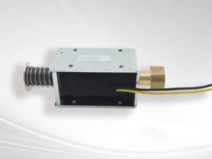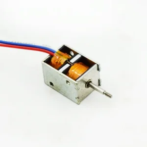


A Bistable Solenoid is a specialized electromagnetic actuator designed to provide two stable mechanical positions while requiring electrical energy primarily during the transition between those positions. Unlike a conventional monostable solenoid, which normally needs continuous electrical power to maintain its energized position, a Bistable Solenoid can remain in either of its stable states after the excitation pulse has ended.
Understanding how a Bistable Solenoid works requires looking inside the actuator rather than focusing only on its external dimensions or rated voltage. The performance of a bistable actuator is determined by the interaction of several critical components: the coil, plunger, permanent magnet, magnetic circuit, springs, housing, guide structure, and mechanical interface. Each component has a specific function, but none operates independently. Changing the coil, for example, can influence magnetic force and temperature; changing the permanent magnet can affect both holding force and release energy; changing the plunger geometry can alter the magnetic circuit and force-stroke curve.
From the perspective of an experienced electromagnet manufacturer, the anatomy of a Bistable Solenoid should therefore be understood as an integrated electromagnetic-mechanical system. This article examines each major component, explains its role, discusses the engineering trade-offs involved, and shows how a custom Bistable Solenoid manufacturer can optimize these components for OEM applications.
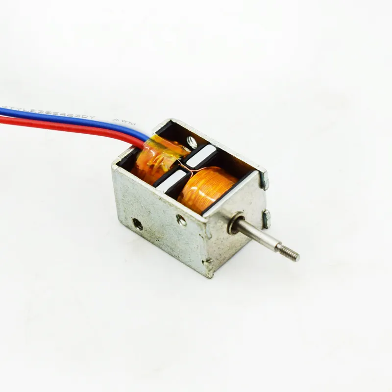
1. Bistable Solenoid Anatomy: Understanding the Complete Structure
Before examining individual components, it is useful to understand the basic architecture of a Bistable Solenoid.
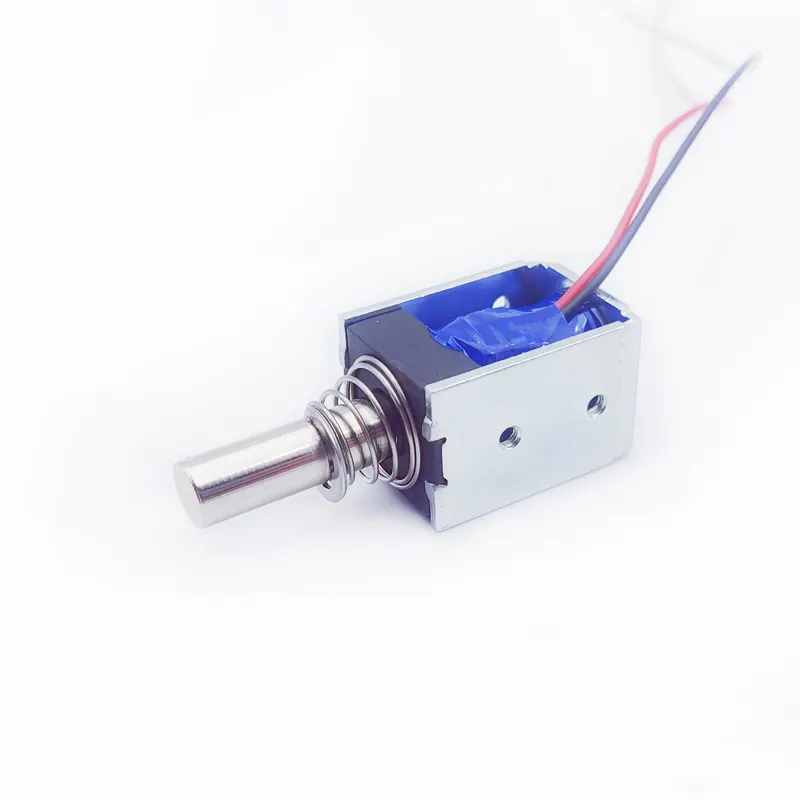
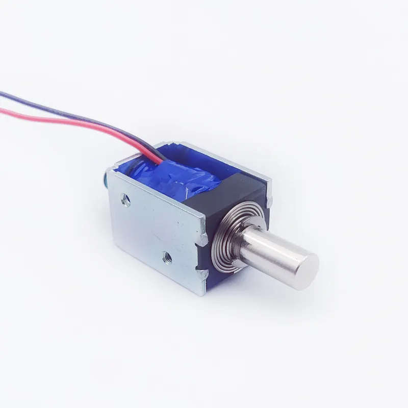
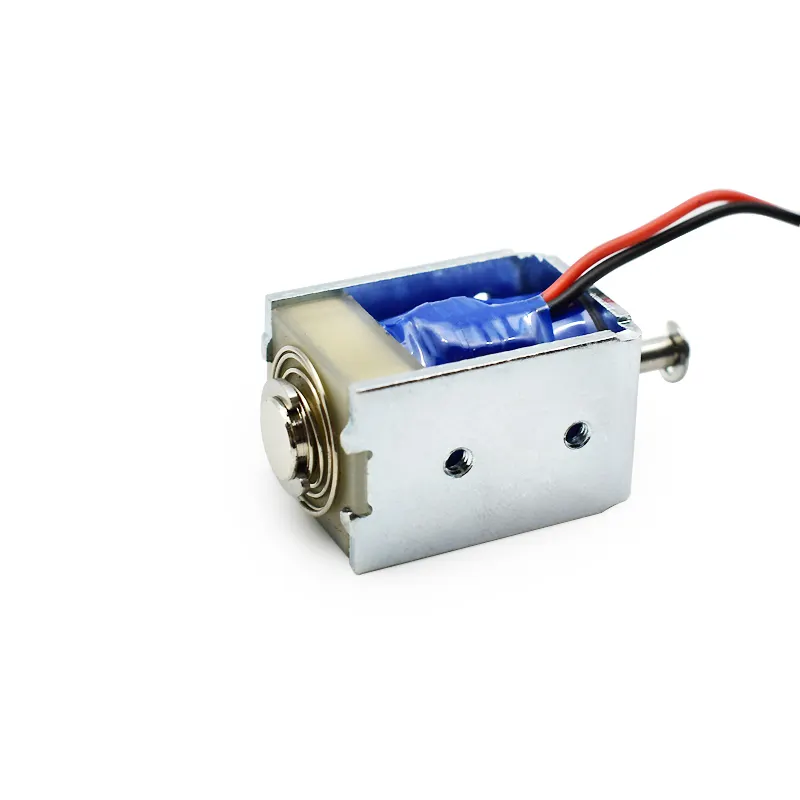
A typical bistable electromagnetic actuator may contain:
- Electromagnetic coil
- Movable plunger or armature
- Permanent magnet
- Magnetic yoke or core
- Housing
- Guide structure
- Spring or springs, depending on design
- Electrical terminals or lead wires
- Mechanical output interface
The exact configuration varies according to the intended application. Some Bistable Solenoid designs rely primarily on permanent-magnetic latching, while others combine magnetic and mechanical elements to establish two stable states.
The operating concept can be simplified into four stages:
1. Initial stable state → 2. Electrical pulse → 3. Magnetic/mechanical transition → 4. New stable state
The coil creates a temporary magnetic field. This field interacts with the permanent magnet and magnetic circuit, reducing or redirecting the existing magnetic holding force and producing movement of the plunger. Once the plunger reaches the opposite stable position, the magnetic circuit can retain it without continuous coil energization.
A useful engineering representation is:
Electrical energy → Magnetic field → Electromagnetic force → Mechanical movement → Stable mechanical state
The quality of this energy conversion depends on the precise relationship between the individual components.
2. Bistable Solenoid Coil: The Electromagnetic Power Source
The coil is one of the most recognizable components of a Bistable Solenoid, but its function is more sophisticated than simply generating magnetic force.
The coil consists primarily of insulated copper wire wound around a bobbin, core, or designated magnetic structure. When current passes through the winding, it creates a magnetic field.
Important coil parameters include:
- Rated voltage
- Coil resistance
- Number of turns
- Wire diameter
- Inductance
- Current
- Pulse duration
- Winding dimensions
- Insulation system
- Temperature rise
For a Bistable Solenoid, the coil often operates differently from the coil in a continuously energized conventional solenoid. The coil may receive a relatively short electrical pulse specifically intended to change the magnetic state of the actuator.
This means the coil must be designed around pulse performance.
A coil that looks attractive based on nominal wattage may not necessarily be the best solution. The engineer must consider how quickly current rises, how much magnetic field is generated, how long the pulse lasts, and how the magnetic circuit responds.
The relationship between coil turns and current can be considered conceptually through magnetomotive force:
Magnetomotive Force ≈ N × I
where N represents the number of turns and I represents current.
However, actual actuator force depends on the complete magnetic circuit, including the air gap, magnetic material, plunger geometry, and saturation behavior.
Therefore, an experienced custom Bistable Solenoid manufacturer does not design the coil in isolation.
3. Bistable Solenoid Plunger: The Moving Mechanical Element
The plunger is the component that physically moves when the magnetic circuit changes.
It is commonly manufactured from a ferromagnetic material selected for appropriate magnetic and mechanical properties. Its geometry can include a cylindrical body, stepped profile, special pole shape, threaded end, slot, hole, or other mechanical interface depending on the customer’s application.
The plunger performs two jobs simultaneously.
First, it participates in the magnetic circuit.
Second, it provides the mechanical output required by the customer’s mechanism.
This makes plunger design particularly important.
Important plunger parameters include:
- Diameter
- Length
- Stroke
- Pole geometry
- Material
- Surface finish
- Plating or surface treatment
- Guide clearance
- Output interface
The plunger must move smoothly through the guide while maintaining the required magnetic relationship with the core and permanent magnet.
Excessive clearance can cause undesirable movement or alignment problems. Insufficient clearance can increase friction and create switching failures.
A Bistable Solenoid may have sufficient theoretical electromagnetic force but still fail in an application because the plunger experiences excessive friction.
This is why plunger geometry and mechanical tolerances should be evaluated together with magnetic performance.

4. Bistable Solenoid Permanent Magnet: Creating the Two Stable States
The permanent magnet is one of the most important components distinguishing many Bistable Solenoid designs from conventional solenoids.
Its purpose is not simply to increase magnetic strength.
Instead, the permanent magnet contributes to the latching function that allows the actuator to maintain a stable position after the coil has been de-energized.
When the plunger reaches one end position, the permanent magnet can establish a low-reluctance magnetic path that produces holding force.
This allows the actuator to remain in that position without continuously energizing the coil.
When the switching pulse is applied, the coil generates a magnetic field that interacts with the permanent magnet’s magnetic field.
The objective is to temporarily modify the magnetic energy state so that the existing latch can be released and the plunger can move toward the opposite position.
This creates an important engineering balance:
Holding Force ↔ Release Force ↔ Switching Energy
If the permanent magnet is too weak, the actuator may not hold its position reliably against vibration, shock, or external load.
If it is too strong, the coil may require excessive energy to release the existing state.
Therefore, permanent magnet selection must consider:
- Magnetic strength
- Dimensions
- Temperature characteristics
- Magnetic circuit geometry
- Position
- Polarity
- Operating environment
- Required holding force
A professional Bistable Solenoid factory should evaluate the permanent magnet as part of the entire magnetic circuit rather than treating it as an independent component.
5. Bistable Solenoid Magnetic Circuit: Connecting the Components
The coil, plunger, permanent magnet, and magnetic yoke work together through the magnetic circuit.
The magnetic circuit determines how magnetic flux travels through the actuator.
A typical path may include:
Permanent Magnet → Magnetic Yoke → Plunger → Air Gap → Core/Yoke → Return Path
The actual configuration depends on the design.
The goal is to create an efficient magnetic path with controlled reluctance and appropriate force at the required positions.
One of the most important variables is the air gap.
Air has much higher magnetic reluctance than typical ferromagnetic materials. Therefore, even relatively small changes in air gap can significantly influence magnetic performance.
The magnetic circuit must be designed to achieve several objectives:
- Adequate starting force
- Reliable switching
- Sufficient holding force
- Appropriate release force
- Controlled magnetic saturation
- Efficient use of coil energy
- Stable operation across manufacturing tolerances
This explains why two solenoids with apparently similar dimensions can have very different force characteristics.
Their internal magnetic circuits may be fundamentally different.
For a custom Bistable Solenoid manufacturer, magnetic-circuit optimization is often one of the most important parts of the engineering process.
6. Bistable Solenoid Springs: When and Why Are Springs Used?
Not every Bistable Solenoid requires the same spring arrangement.
Some bistable designs can rely primarily on magnetic latching, while others use springs to control position, preload, return behavior, shock resistance, or mechanical stability.
When a spring is incorporated, its force becomes an important part of the actuator’s overall force balance.
A simplified relationship can be expressed as:
Net Mechanical Force = Electromagnetic Force − Magnetic Holding Force − Spring Force − Friction − External Load
The spring may perform several functions.
Position Control
The spring can bias the plunger toward a particular direction.
Mechanical Preload
A controlled spring force can help eliminate unwanted movement or mechanical play.
Return Assistance
In some architectures, the spring contributes to movement toward one of the stable positions.
Shock and Vibration Management
A spring can influence how the plunger responds to external mechanical disturbances.
Spring design parameters include:
- Spring rate
- Free length
- Working length
- Preload
- Maximum compression
- Material
- Fatigue characteristics
- Operating temperature
An incorrectly selected spring can prevent the actuator from switching even if the electromagnetic design is otherwise correct.
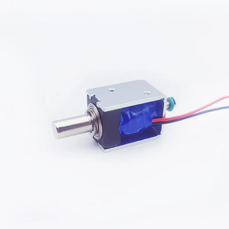
7. Bistable Solenoid Force Balance: How the Components Work Together
The real behavior of a Bistable Solenoid emerges from the interaction between all its components.
Consider a plunger initially locked in Position A.
The permanent magnet creates holding force.
The spring may apply an opposing or assisting force.
The mechanical load may resist movement.
Friction exists between the plunger and guide.
When the electrical pulse is applied, the coil produces electromagnetic force.
The actuator switches only if the available force and magnetic energy are sufficient to overcome the combined resistance.
Conceptually:
F_net = F_electromagnetic − F_magnetic holding − F_spring − F_friction − F_external
This relationship changes continuously as the plunger moves.
The air gap changes.
The spring position changes.
The magnetic circuit changes.
The external load may change.
Therefore, a Bistable Solenoid cannot be accurately characterized by one force number alone.
Engineers often need to examine:
- Starting force
- Force at intermediate stroke
- End-of-stroke force
- Holding force
- Release force
- Spring force
- Friction
- External load
This is why force-stroke testing is valuable during custom actuator development.
8. Bistable Solenoid Housing and Guide Structure
Although the housing may appear to be a relatively passive component, it can significantly influence the performance of a Bistable Solenoid.
The housing provides mechanical protection and establishes the relative positions of the coil, magnetic circuit, and moving plunger.
It may also serve as part of the magnetic path, depending on the design.
Important housing considerations include:
- Material
- Wall thickness
- Internal dimensions
- Magnetic properties
- Mounting structure
- Dimensional stability
- Corrosion resistance
- Heat dissipation
The guide structure is equally important.
The plunger must move with controlled clearance.
If the guide is too tight, friction can increase.
If the guide is too loose, the plunger may experience excessive lateral movement.
Both conditions can affect switching reliability.
For high-volume OEM production, dimensional consistency is particularly important.
A small variation in guide diameter or plunger diameter can change friction and therefore influence the force margin available for switching.
This is one reason why a professional Bistable Solenoid factory needs to control machining, component tolerances, and assembly processes—not just final electrical testing.
9. Bistable Solenoid Surface Treatment and Material Selection
Material selection influences both electromagnetic and mechanical performance.
The plunger and magnetic components require materials with suitable magnetic characteristics, while mechanical components may prioritize strength, wear resistance, corrosion resistance, or dimensional stability.
Important material considerations include:
- Magnetic permeability
- Saturation characteristics
- Mechanical strength
- Hardness
- Machinability
- Corrosion resistance
- Temperature stability
The plunger surface may also require treatment or plating.
Depending on the application, surface treatment can influence:
- Friction
- Wear
- Corrosion
- Surface hardness
- Dimensional stability
- Compatibility with lubrication
However, there is no universal “best” plating for every Bistable Solenoid.
The appropriate choice depends on the base material, guide material, surface roughness, operating environment, lubrication, temperature, and required lifetime.
A custom actuator for an indoor office device may have very different material requirements from an actuator used in industrial equipment exposed to moisture, dust, vibration, or temperature cycling.

10. Bistable Solenoid Coil and Thermal Management
One of the attractive characteristics of a Bistable Solenoid is that its coil normally does not need to remain energized while the actuator is stationary.
This can reduce average heat generation compared with a continuously energized monostable actuator.
However, thermal design is still important.
During switching, the coil may experience a relatively high current pulse.
The resulting heat depends on factors including:
- Coil resistance
- Pulse current
- Pulse duration
- Switching frequency
- Ambient temperature
- Housing design
- Heat dissipation
Copper resistance also changes with temperature.
As coil temperature increases, resistance generally increases, which can influence current in a voltage-driven system.
Therefore, a Bistable Solenoid should be evaluated over its actual operating conditions.
For example, a design may work correctly at room temperature but have reduced switching margin at high temperature if coil resistance, permanent magnet characteristics, friction, or mechanical tolerances change.
Professional design validation may therefore consider:
| Parameter | Thermal Consideration |
|---|---|
| Coil resistance | Changes with temperature |
| Pulse current | Influences instantaneous heating |
| Pulse duration | Affects energy per switching event |
| Switching frequency | Determines average thermal load |
| Ambient temperature | Changes operating conditions |
| Housing | Influences heat dissipation |
| Magnet | Temperature can affect magnetic behavior |
| Lubrication | Temperature can influence friction |
Thermal behavior should therefore be considered during the initial design rather than added as an afterthought.
11. Bistable Solenoid Force-Stroke and Tolerance Design
A Bistable Solenoid must operate reliably despite inevitable manufacturing tolerances.
No production component is perfectly identical to another.
Variations can occur in:
- Coil resistance
- Plunger diameter
- Guide diameter
- Air gap
- Magnet strength
- Spring force
- Housing dimensions
- Assembly position
The design therefore needs an appropriate performance margin.
For example, suppose a prototype switches correctly with a large force margin. If the design is sensitive to a 0.05 mm dimensional variation, mass production may produce inconsistent switching behavior.
This is why experienced custom Bistable Solenoid manufacturers pay attention to tolerance stack-up.
A typical engineering evaluation can include:
Component tolerance → Magnetic performance variation → Mechanical friction variation → Switching margin → Production reliability
Force-stroke testing can help reveal these relationships.
Instead of asking only:
“Does the prototype work?”
the engineering team should ask:
“Does the design remain reliable across the expected manufacturing and operating tolerance range?”
That question is much more important when moving from prototype quantities to mass production.
12. Bistable Solenoid Control and Component Interaction
The anatomy of a Bistable Solenoid does not end with its mechanical components. The actuator is part of an electrical control system.
The coil must receive an appropriate electrical pulse to change the magnetic state.
Depending on the design, the controller may need to manage:
- Pulse polarity
- Pulse voltage
- Pulse duration
- Current
- Switching timing
- Electrical protection
A common architecture for polarity-controlled bistable actuators is an H-bridge, although the appropriate circuit depends on the actual actuator configuration.
This is an important difference between a Bistable Solenoid and a basic monostable solenoid.
The customer cannot evaluate the actuator independently of the driver.
For example, a Bistable Solenoid may perform correctly when supplied with a laboratory power source but fail when integrated into the customer’s PCB because the actual driver cannot provide sufficient pulse current or duration.
Therefore, during OEM development, the actuator and driver should be validated together.
A professional manufacturer can provide the electrical characteristics needed by the customer’s engineering team so that the control system can be designed appropriately.

13. Bistable Solenoid Applications and Component Priorities
Different applications place different priorities on the anatomy of the actuator.
Smart Locks
The permanent magnet and magnetic circuit are especially important because the actuator needs reliable two-state retention while minimizing battery consumption.
Battery-Powered Metering Equipment
Coil efficiency, pulse energy, and mechanical reliability can be critical because the actuator may switch relatively infrequently but must operate reliably over a long product lifetime.
Valves
The plunger interface, force-stroke curve, sealing mechanism, and environmental resistance may become particularly important.
Vending Equipment
The actuator may need a compact structure, controlled stroke, and reliable switching under repeated cycles.
Office Equipment
Low noise, compact dimensions, controlled friction, and reliable switching can be important.
Industrial Automation
Force, lifetime, environmental resistance, vibration, mounting structure, and dimensional repeatability may have higher priority.
This demonstrates why there is no single universal Bistable Solenoid design.
The anatomy must be adapted to the application.
14. Custom Bistable Solenoid Design: How SF Optimizes the Complete Assembly
For an OEM customer, developing a custom Bistable Solenoid is often more effective when the manufacturer evaluates the entire actuator rather than modifying only one component.
SF is a professional customized electromagnet manufacturer with more than 10 years of experience. Our experienced engineering team works with customers to develop electromagnetic solutions according to their application and product requirements.
SF operates a 6,000 m² factory, providing manufacturing capacity for customized electromagnets and solenoids. We have helped many brand customers customize different types of electromagnets, with products exported to more than 60 countries and regions.
For a Bistable Solenoid project, the engineering process can evaluate:
| Component | Key Engineering Factors |
|---|---|
| Coil | Voltage, resistance, turns, pulse, thermal behavior |
| Plunger | Material, geometry, stroke, surface finish |
| Permanent magnet | Holding force, temperature, dimensions, polarity |
| Magnetic yoke | Flux path, saturation, reluctance |
| Spring | Preload, spring rate, return force |
| Housing | Dimensions, mounting, protection, heat dissipation |
| Guide | Clearance, friction, alignment |
| Electrical interface | Wires, terminals, connector |
| Assembly | Position tolerances and consistency |
| Testing | Force, stroke, pulse response, reliability |
The key principle is system optimization.
For example, increasing permanent magnet strength without considering coil capability may make switching more difficult. Increasing spring force may improve mechanical return behavior but require greater electromagnetic force. Reducing guide clearance may improve positioning but increase friction.
Every modification has consequences.
That is why cooperation with an experienced custom Bistable Solenoid manufacturer can be valuable during product development.
15. How to Choose a Bistable Solenoid Factory for OEM Production
Selecting a Bistable Solenoid factory should involve more than comparing catalog specifications and unit prices.
OEM customers should evaluate whether the manufacturer understands the relationship between electromagnetic design and manufacturing processes.
Important questions include:
Does the manufacturer have electromagnetic engineering capability?
A true manufacturer should be able to discuss magnetic circuits, force-stroke characteristics, coil design, air gaps, materials, and thermal behavior.
Can the manufacturer customize the actuator?
A custom project may require changes to the coil, plunger, permanent magnet, spring, housing, mounting structure, or electrical interface.
Can the manufacturer support prototype development?
The transition from concept to prototype is an important stage in identifying design problems.
Can the manufacturer control production consistency?
The actuator should not simply work on the first prototype. Production processes must reproduce the required performance consistently.
Can the manufacturer perform functional testing?
Depending on the application, this may include electrical, mechanical, force, stroke, switching, thermal, or life testing.
For customers looking for a China Bistable Solenoid manufacturer, these engineering and manufacturing capabilities are often more meaningful than simply selecting a supplier based on location.
SF combines customized electromagnetic engineering with manufacturing capability and experience serving customers across multiple international markets.

Bistable Solenoid Anatomy: Frequently Asked Questions
What are the main components of a Bistable Solenoid?
The major components can include an electromagnetic coil, plunger, permanent magnet, magnetic yoke or core, housing, guide structure, springs, and electrical interface. The exact configuration depends on the actuator design.
What does the coil do in a Bistable Solenoid?
The coil generates a temporary magnetic field when energized. This magnetic field changes the magnetic state of the actuator and provides the energy needed to switch the plunger between stable positions.
What is the function of the permanent magnet?
The permanent magnet provides magnetic holding force that helps maintain the actuator in a stable position after the coil has been de-energized.
Does every Bistable Solenoid use a spring?
No. The exact spring arrangement depends on the design. Some Bistable Solenoid architectures rely primarily on magnetic latching, while others use springs to provide preload, return force, positioning, or mechanical assistance.
Why is the plunger important?
The plunger is both a magnetic component and a mechanical output component. Its material, geometry, surface finish, alignment, and clearance can significantly affect force, friction, stroke, and switching reliability.
Why is the air gap important?
The air gap has a major influence on magnetic reluctance and therefore electromagnetic performance. Small dimensional changes can affect force and switching behavior.
Can all Bistable Solenoids use the same coil?
No. Coil design depends on voltage, pulse duration, current, magnetic circuit, required force, dimensions, thermal conditions, and application requirements.
Can a Bistable Solenoid be customized?
Yes. A professional custom Bistable Solenoid manufacturer can customize the coil, plunger, permanent magnet, spring, housing, magnetic circuit, mounting structure, and electrical interface according to application requirements.
Understanding the Anatomy of a Bistable Solenoid
The anatomy of a Bistable Solenoid is best understood as an integrated electromagnetic and mechanical system.
The coil provides the temporary electromagnetic field required for switching.
The permanent magnet provides magnetic energy for stable position retention.
The plunger converts electromagnetic force into mechanical movement while simultaneously participating in the magnetic circuit.
The spring, when used, provides controlled mechanical force, preload, return assistance, or positioning.
The magnetic yoke and housing establish the magnetic and mechanical framework that connects these components.
The guide structure and manufacturing tolerances determine whether the theoretical design can perform consistently in actual production.
These components are highly interdependent.
A stronger permanent magnet can increase holding force but may require greater switching energy. A stronger spring can improve mechanical behavior but increase the electromagnetic force requirement. A different plunger geometry can improve magnetic performance but change friction or stroke characteristics. A modified coil can increase switching force but also affect resistance, heat, dimensions, and driver requirements.
This is why designing a reliable Bistable Solenoid is fundamentally an exercise in system optimization.
The key design relationship can be summarized as:
Coil + Permanent Magnet + Magnetic Circuit + Plunger + Spring + Mechanical Structure + Control System = Bistable Solenoid Performance
For OEM customers, selecting an experienced custom Bistable Solenoid manufacturer is therefore an important part of the product-development process.
With more than 10 years of customized electromagnet manufacturing experience, an experienced engineering team, a 6,000 m² factory, extensive customization experience, and products exported to more than 60 countries and regions, SF provides customized electromagnetic solutions for brand and OEM customers.
Whether the requirement is a compact battery-powered actuator, smart locking mechanism, industrial switching device, valve actuator, vending mechanism, or another two-position electromagnetic application, the correct Bistable Solenoid should be developed around the actual system requirements.
The best actuator is not necessarily the one with the strongest magnet, largest coil, or highest nominal force. It is the one in which magnetic force, holding force, release force, mechanical movement, spring behavior, thermal performance, tolerances, and control electronics are properly balanced.
That integrated engineering approach is the foundation of a reliable, manufacturable, and application-specific Bistable Solenoid.
Custom all kinds of electromagnet, contact SF electromagnet factory whatsapp +86 189 0261 1680