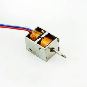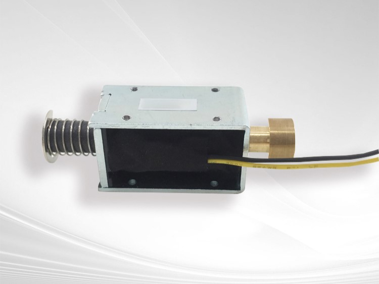










A Bistable Solenoid is a specialized electromagnetic actuator designed to move between and remain in two stable mechanical positions. Unlike a conventional solenoid that typically requires continuous electrical power to maintain its actuated position, a Bistable Solenoid can use a short electrical pulse to change state and then remain in that state with little or no continuous power.
This characteristic makes the Bistable Solenoid particularly valuable in battery-powered equipment, smart locks, valves, metering systems, dispensing equipment, industrial automation, office equipment, and other applications where low standby power and reliable two-position control are important.
But how does a Bistable Solenoid actually work?
From an electromagnetic engineering perspective, the answer involves the interaction of a coil, magnetic circuit, permanent magnet, plunger, air gap, mechanical load, and pulse-control circuit. The actuator must generate enough electromagnetic force to overcome the existing magnetic holding force and mechanical resistance, move the plunger through its required stroke, and establish a new stable magnetic state.
This article explains how Bistable Solenoids work, how their magnetic latching mechanism operates, how coil and plunger design affect performance, why air gaps and force-stroke curves matter, and how OEM customers can work with a custom Bistable Solenoid manufacturer to develop a reliable actuator.
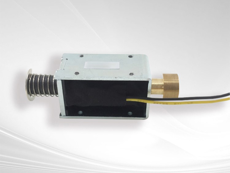
1. How Does a Bistable Solenoid Work?
The simplest way to understand how a Bistable Solenoid works is to think of it as a two-position electromagnetic actuator.
A conventional solenoid generally has one stable position when power is removed. When voltage is applied, the magnetic field pulls the plunger into the energized position. When the power disappears, a spring or external mechanical force usually returns the plunger.
A Bistable Solenoid works differently.
It is designed so that the plunger can remain stable in Position A or Position B. An electrical pulse changes the actuator from one state to the other. After the pulse ends, the magnetic or mechanical latching structure maintains the new position.
A simplified operating sequence is:
Stable Position A → Electrical Pulse → Magnetic Release → Plunger Movement → Stable Position B
A second pulse can then reverse the process:
Stable Position B → Reverse/Controlled Pulse → Magnetic Release → Plunger Movement → Stable Position A
Therefore, the defining characteristic of a Bistable Solenoid is not simply its electromagnetic coil. It is the combination of electromagnetic switching and two-state latching.
The exact construction can vary considerably between products. Some designs use permanent magnets and polarity-reversing pulses, while others use more complex magnetic circuits or mechanical structures.
For an OEM actuator, the correct architecture depends on stroke, force, voltage, switching frequency, available power, environmental conditions, and installation constraints.
2. Bistable Solenoid Working Principle: The Role of the Magnetic Field
The basic operating principle begins with the electromagnetic coil.
When electrical current flows through a coil, it creates a magnetic field. The strength and distribution of this magnetic field depend on several factors, including:
- Número de vueltas de la bobina
- Actual
- Magnetic core geometry
- Material magnético
- Entrehierro
- Coil dimensions
- Magnetic circuit design
When the coil is energized, the magnetic circuit produces a force on the movable plunger.
However, in a Bistable Solenoid, the coil does more than simply attract a plunger.
The electromagnetic pulse must also interact with the existing magnetic field produced by the permanent magnet or magnetic latching structure.
This creates a controlled change in the magnetic circuit.
For example, consider a simplified bistable structure with two stable positions:
Position A
The permanent magnet creates a magnetic flux path that strongly holds the plunger against one magnetic pole.
When the switching coil receives an appropriate electrical pulse, its magnetic field modifies the existing magnetic flux.
If the coil-generated magnetic field is oriented correctly, it can:
- Reduce the existing holding force.
- Release the plunger.
- Generate an attractive force toward Position B.
- Move the plunger through the required stroke.
- Establish a new magnetic flux path.
- Allow the plunger to remain in Position B after the pulse ends.
This is the fundamental reason a Bistable Solenoid can change position without requiring continuous electrical power.
3. How Bistable Solenoid Magnetic Latching Works
El magnetic latching mechanism is one of the most important differences between a conventional solenoid and a Bistable Solenoid.
A permanent magnet is often incorporated into the magnetic circuit so that the actuator has a stable magnetic energy state at each end position.
Imagine the plunger is initially located at Position A.
The permanent magnet generates magnetic flux through the magnetic circuit. Because the magnetic reluctance is relatively low when the plunger is correctly positioned, the system naturally tends to remain in that state.
This creates the first stable position.
When a suitable electrical pulse is applied, the coil temporarily changes the magnetic field.
The coil does not necessarily need to provide continuous force throughout the entire operating period. Instead, it needs to provide enough electromagnetic energy to change the magnetic state of the actuator.
Once the plunger moves toward Position B, the magnetic circuit becomes favorable for the second stable state.
After the pulse ends, the permanent magnet can continue to provide the holding force.
The process can therefore be summarized as:
| Stage | Magnetic Condition | Plunger Condition |
|---|---|---|
| 1 | Stable magnetic circuit | Position A |
| 2 | Coil energized | Existing magnetic state disrupted |
| 3 | Magnetic force changes | Plunger begins moving |
| 4 | Magnetic circuit shifts | Plunger approaches Position B |
| 5 | New magnetic path established | Position B reached |
| 6 | Coil de-energized | Position B maintained |
The engineering challenge is to ensure that the magnetic force profile supports reliable movement throughout the entire transition.
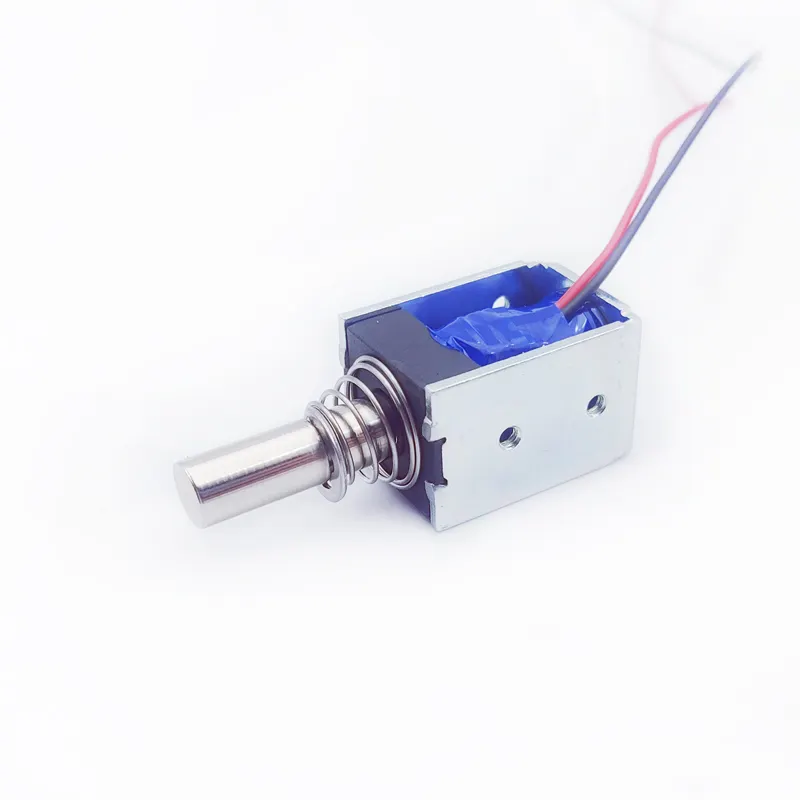
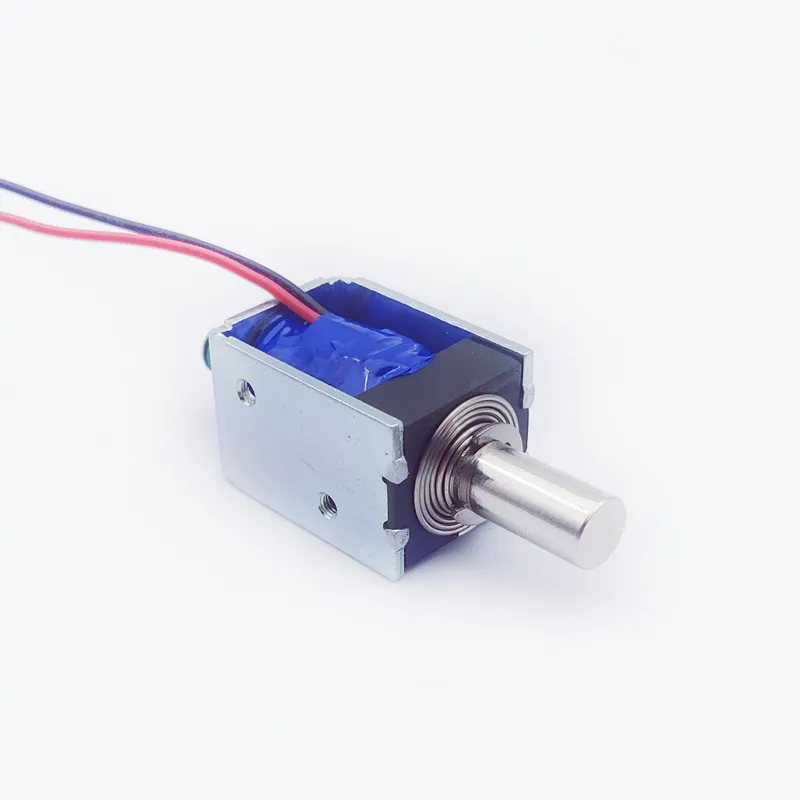
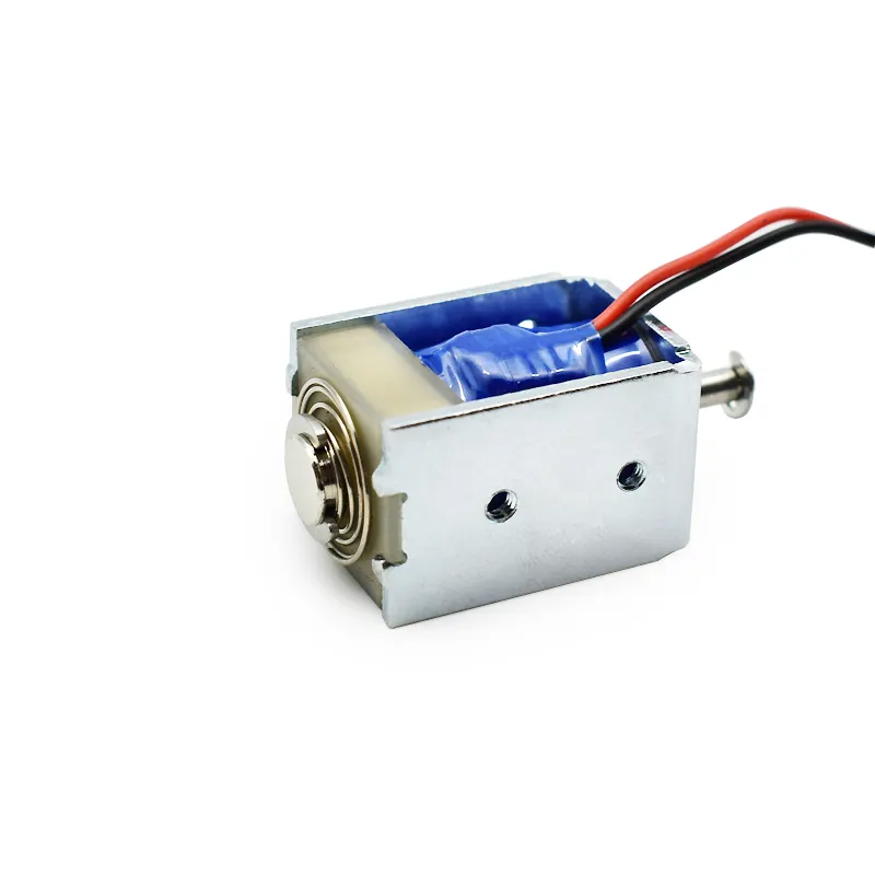
4. How a Bistable Solenoid Uses Electrical Pulses
A major advantage of a Bistable Solenoid is that it generally does not need continuous electrical power for position holding.
Instead, the control system provides a pulse.
The pulse characteristics depend on the specific actuator design.
Important parameters include:
- Voltaje
- Actual
- Pulse duration
- Polarity
- Rise time
- Fall time
- Switching frequency
- Minimum operating voltage
- Maximum operating voltage
For example, a bistable actuator may be designed so that one pulse polarity moves the actuator in one direction and the opposite polarity moves it back.
Conceptually:
Positive Pulse → Position A → Position B
Negative Pulse → Position B → Position A
However, not every Bistable Solenoid uses exactly the same electrical architecture. The control method must be designed around the specific magnetic circuit.
This is important for OEM integration.
A customer should not assume that every bistable actuator can be driven by simply connecting it directly to a DC voltage source.
The pulse driver may require:
- H-bridge control
- Polarity reversal
- Transistor switching
- Capacitor discharge
- Pulse-width control
- Current limiting
- Electrical protection
Therefore, the actuator and its control circuit should be considered as an integrated system during product development.
5. Bistable Solenoid Coil: How the Coil Creates Switching Force
The coil is the electromagnetic energy-conversion component of the Bistable Solenoid.
When current passes through the coil, it creates magnetomotive force that changes the magnetic flux distribution.
A simplified relationship is:
Magnetomotive Force ≈ Number of Turns × Current
In practical engineering, however, the actual force is determined by the complete magnetic circuit.
Important variables include:
- Coil turns
- Wire diameter
- Actual
- Resistencia de la bobina
- Inductance
- Material principal
- Magnetic path
- Entrehierro
- Plunger position
- Temperatura
The coil therefore cannot be optimized independently.
For example, increasing the number of turns may increase magnetomotive force, but it can also increase resistance, affect current, increase winding volume, and influence the dynamic response.
Increasing current can increase electromagnetic force, but it can also increase heating and place greater demands on the electronic driver.
Por eso, con experiencia custom Bistable Solenoid manufacturers typically optimize coil specifications together with the magnetic circuit rather than simply increasing coil power.
6. How Bistable Solenoid Plunger Movement Occurs
The plunger is the moving component that converts electromagnetic energy into mechanical movement.
During a switching event, the plunger must overcome several forces.
A useful conceptual model is:
Net Force = Electromagnetic Force − Magnetic Holding Resistance − Spring Force − Friction − External Load
This equation is simplified, but it highlights an important engineering principle:
The coil’s nominal force alone does not determine whether the actuator will switch.
Suppose a Bistable Solenoid has a strong magnetic holding force in Position A.
The switching pulse first has to overcome this holding force.
After the plunger starts moving, the force balance changes because:
- Air gap changes
- Magnetic reluctance changes
- Spring force may change
- External load may change
- Friction may vary
- Magnetic saturation may change
Consequently, the actuator’s performance must be evaluated over the entire stroke, not just at the beginning or end.
This is why force-stroke measurement is an important part of professional solenoid development.
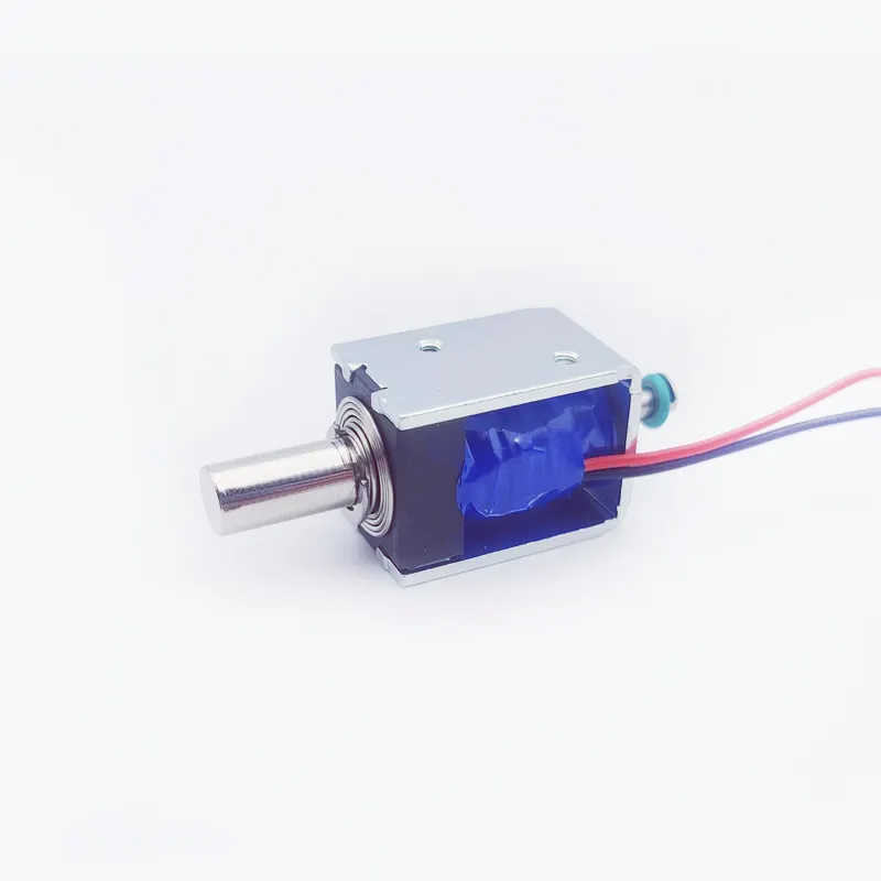
7. Bistable Solenoid Air Gap and Magnetic Force
The air gap is one of the most sensitive parameters in electromagnetic actuator design.
Magnetic flux prefers a low-reluctance path. Air has substantially higher magnetic reluctance than ferromagnetic materials.
Therefore, even a relatively small air gap can significantly influence magnetic performance.
In a Bistable Solenoid, the effective air gap affects:
- Starting force
- Holding force
- Switching force
- Magnetic efficiency
- Response time
- Power requirements
- Position stability
The challenge is particularly important because manufacturing tolerances can alter the actual magnetic gap.
For example, variations in:
- Plunger diameter
- Pole geometry
- Housing dimensions
- Assembly position
- Surface flatness
- Magnetic component thickness
can affect the final magnetic circuit.
Un profesional Bistable Solenoid factory therefore needs to control critical dimensions carefully.
This is one reason why electromagnetic actuator manufacturing cannot be reduced to simply winding copper wire around an iron core.
8. Bistable Solenoid Force-Stroke Curve
One of the most important engineering concepts when understanding how Bistable Solenoids work is the force-stroke relationship.
A solenoid does not necessarily generate a constant force throughout its movement.
Instead, electromagnetic force changes as the plunger position changes.
At the same time, the mechanical load may also change.
For example, a spring may require progressively greater force as it compresses.
Therefore, engineers need to compare:
Available electromagnetic force vs. required mechanical force throughout the stroke
A typical evaluation may examine:
| Plunger Position | Electromagnetic Force | Mechanical Resistance | Resultado |
|---|---|---|---|
| Start | High/defined by magnetic circuit | Holding + friction + load | Must release |
| Mid-stroke | Position-dependent | Load changes | Must continue moving |
| Near end | Position-dependent | End-position forces | Must complete stroke |
| Stable state | Holding force | External disturbance | Must remain stable |
The exact values depend entirely on the actuator design.
For OEM projects, the most useful specification is therefore often a force-stroke curve, rather than a single maximum-force number.
This is particularly important when a Bistable Solenoid is integrated into a mechanism with variable load.
9. Why Bistable Solenoid Does Not Need Continuous Holding Power
The low-power characteristic of a Bistable Solenoid comes directly from its latching mechanism.
Consider a conventional solenoid holding a mechanical lock.
If the solenoid requires continuous current, the coil consumes electrical power continuously:
Power = Voltage × Current
That continuous power also produces heat.
A Bistable Solenoid changes this energy model.
Instead of continuously powering the coil, the controller supplies energy primarily when the state needs to change.
Once the plunger reaches the new stable position, the permanent magnet or mechanical latch maintains the state.
This can reduce:
- Standby power
- Coil heating
- Battery drain
- Continuous electrical loading
This characteristic is particularly useful when an actuator changes state only occasionally.
Examples include:
- cerraduras inteligentes
- Battery-operated meters
- Portable equipment
- Remote valves
- Access systems
- Energy-saving control devices
However, the total system energy consumption still depends on switching frequency and pulse characteristics.
A Bistable Solenoid that switches hundreds of times per minute is obviously different from one that changes state only once every few hours.

10. Bistable Solenoid vs. Monostable Solenoid
Understanding the difference between bistable and monostable operation makes the working principle much easier to understand.
| Feature | Monostable Solenoid | Bistable Solenoid |
|---|---|---|
| Stable states | Typically one | Two |
| Holding mechanism | Often spring/mechanical | Magnetic/mechanical latching |
| Continuous power | Often needed for holding | Generally unnecessary for holding |
| Switching | Usually energize/de-energize | Pulse-based state change |
| Standby consumption | Can be significant | Typically very low |
| Battery suitability | Application-dependent | Often advantageous |
| Control circuit | Usually simpler | Often more specialized |
| Two-position retention | Usually requires additional mechanism | Integrated into actuator design |
A monostable solenoid is often preferable when the mechanism naturally needs to return to a default position after power is removed.
A Bistable Solenoid becomes particularly useful when the application needs the actuator to remember its last mechanical state without continuous electrical power.
This distinction is important during the initial system architecture stage.
11. How Bistable Solenoid Performance Changes With Temperature
Temperature is an important consideration for any electromagnetic actuator.
For a Bistable Solenoid, temperature can influence both the electrical and magnetic characteristics.
Copper coil resistance changes with temperature. As temperature increases, resistance generally increases.
This can influence coil current when the actuator is driven by a voltage-controlled circuit.
Temperature can also affect:
- Magnet performance
- Material properties
- Lubrication
- Fricción
- Mechanical tolerances
- Housing dimensions
- Coil insulation
- Pulse performance
Therefore, an actuator that works at 25°C may not necessarily perform identically at a much higher or lower temperature.
For demanding applications, testing should consider the actual operating environment.
Un profesional custom Bistable Solenoid manufacturer can help define appropriate testing conditions based on:
- Minimum ambient temperature
- Maximum ambient temperature
- Switching frequency
- Pulse duration
- Installation conditions
- Thermal dissipation
- Required lifetime
This is particularly important for automotive, industrial, outdoor, and enclosed equipment.
12. How Bistable Solenoid Mechanical Design Affects Reliability
Electromagnetic design is only one half of the problem.
Mechanical design has an equally important influence on Bistable Solenoid reliability.
The plunger must move smoothly and consistently.
Important mechanical parameters include:
- Plunger alignment
- Guide clearance
- Surface finish
- Plunger straightness
- Housing concentricity
- Spring characteristics
- Mounting tolerance
- External load
- End-stop design
Excessive friction can cause a serious problem.
The magnetic circuit may provide enough theoretical force, but the actual plunger may fail to move because friction consumes too much available force.
Similarly, excessive side loading can create inconsistent performance.
This is why a professional manufacturer needs to consider the electromagnetic-mechanical interface rather than treating the solenoid as an isolated electrical component.
For high-volume production, controlling dimensional tolerances is also essential for maintaining consistent switching performance across batches.
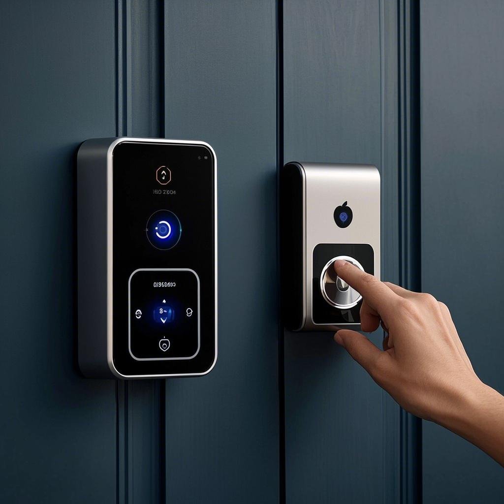
13. Bistable Solenoid Applications
The working principle of a Bistable Solenoid makes it suitable for applications requiring two-position control and low standby power.
Smart Lock Systems
A bistable actuator can switch between locked and unlocked states while minimizing continuous energy consumption.
Battery-Powered Devices
Because the actuator does not normally need continuous power to maintain its state, it can help reduce battery consumption.
Valves
Certain fluid-control architectures can use bistable electromagnetic actuation to maintain open or closed states without continuously energizing the coil.
Metering Equipment
Battery-powered meters may use a Bistable Solenoid when mechanical switching is required but long-term standby power must be minimized.
Vending Machines
The actuator can control locking, dispensing, or mechanical release mechanisms.
Office Equipment
Printers, copiers, document-processing equipment, and other machines can use bistable actuators for low-power mechanical switching.
Automatización industrial
Two-state mechanisms can use bistable electromagnetic actuators for indexing, locking, switching, or positioning functions.
The application determines the appropriate actuator design. Stroke, load, switching frequency, voltage, environment, and lifetime requirements should all be considered before selecting a product.
14. How to Design a Custom Bistable Solenoid
For an OEM project, the development of a custom Bistable Solenoid should begin with the application rather than an existing catalog model.
A professional engineering process can follow several stages.
Step 1: Define the Mechanical Requirements
Determine:
- Ataque
- Installation dimensions
- Mounting method
- Plunger interface
- External load
- Two stable positions
Step 2: Define Electrical Requirements
Specify:
- Nominal voltage
- Voltage tolerance
- Pulse width
- Maximum current
- Switching frequency
- Control method
Step 3: Define the Magnetic Requirements
Determine:
- Holding force
- Release force
- Starting force
- Force-stroke relationship
- Required magnetic margin
Step 4: Define Environmental Conditions
Consider:
- Temperatura
- Humidity
- Vibration
- Shock
- Dust
- Corrosion
- Installation orientation
Step 5: Develop the Prototype
The manufacturer can optimize the magnetic circuit, coil, plunger, magnet, housing, and mechanical structure.
Step 6: Test the Prototype
Testing should ideally cover:
- Switching reliability
- Force-stroke behavior
- Pulse response
- Holding force
- Release force
- Temperatura
- Mechanical lifetime
Step 7: Production Validation
Once the design is finalized, manufacturing processes and critical dimensions should be controlled to ensure consistent production.
This engineering workflow is particularly useful when developing a custom actuator rather than adapting a standard component.
15. Why Choose SF as a Custom Bistable Solenoid Manufacturer?
Selecting a Bistable Solenoid manufacturer is an important part of OEM product development because actuator performance depends heavily on engineering and manufacturing consistency.
SF is a professional customized electromagnet manufacturer with more than 10 years of experience in electromagnetic product manufacturing.
Our experienced engineering team can work with customers on customized electromagnetic actuator requirements, including mechanical structure, electromagnetic performance, coil specifications, stroke, installation requirements, and application-specific design considerations.
SF operates a 6,000 m² factory, providing manufacturing capacity for customized electromagnet and solenoid projects.
We have helped many brand customers customize different types of electromagnets and solenoids, and our products are exported to more than 60 countries and regions.
For a custom Bistable Solenoid project, the engineering objective is not simply to make a coil generate magnetic force. It is to create a complete actuator in which the following elements work together:
Coil + Magnetic Circuit + Permanent Magnet + Plunger + Air Gap + Mechanical Load + Pulse Control
The design should provide reliable switching while meeting the customer’s dimensional, electrical, mechanical, environmental, and production requirements.
For customers searching for a China Bistable Solenoid manufacturer, SF can provide customized electromagnetic manufacturing support from engineering development through production.

Bistable Solenoid FAQ
How does a Bistable Solenoid work?
A Bistable Solenoid uses electromagnetic pulses to switch a plunger between two stable positions. A permanent magnet or other latching mechanism maintains the selected position after the electrical pulse ends.
Does a Bistable Solenoid consume power when stationary?
Normally, a properly designed Bistable Solenoid does not require continuous coil power to maintain either stable state. Its main electrical energy consumption occurs during state transitions.
How does a Bistable Solenoid switch back?
Depending on the design, the actuator may use a pulse with opposite polarity or another controlled electromagnetic excitation to release the current magnetic state and move the plunger to the opposite stable position.
Why is the permanent magnet important?
The permanent magnet contributes to the magnetic holding force that maintains the actuator’s stable state after the coil has been de-energized.
Can a Bistable Solenoid operate with DC power?
Yes, but the control method is different from simply continuously powering a conventional DC solenoid. The specific Bistable Solenoid determines the required pulse voltage, polarity, current, and duration.
What causes a Bistable Solenoid to fail to switch?
Potential causes include insufficient pulse energy, excessive magnetic holding force, inadequate coil performance, excessive friction, mechanical misalignment, external load, excessive air gap, temperature effects, or manufacturing tolerances.
Can SF customize a Bistable Solenoid?
Yes. SF provides customized electromagnet and solenoid manufacturing and can develop Bistable Solenoid configurations according to customer requirements.
How Bistable Solenoids Work
Understanding how a Bistable Solenoid works requires looking beyond the coil.
The fundamental operating principle is the interaction between the electromagnetic coil and the magnetic latching system. A controlled electrical pulse changes the magnetic field, releases the existing stable state, and generates the force required to move the plunger toward the opposite position. Once the plunger reaches the new position, the magnetic circuit can maintain that state without continuous coil energization.
The complete process can be summarized as:
Electrical Pulse → Magnetic Field Change → Latch Release → Plunger Movement → New Magnetic Circuit → Stable Position
This operating principle gives Bistable Solenoids several important advantages, particularly low standby power consumption, two-position retention, reduced continuous coil heating, and suitability for battery-powered systems.
However, successful Bistable Solenoid engineering requires careful consideration of the magnetic circuit, permanent magnet, coil, air gap, plunger geometry, force-stroke characteristics, mechanical friction, temperature, tolerances, pulse-control system, and application load.
For OEM applications, choosing an experienced custom Bistable Solenoid manufacturer can help ensure that these variables are considered together rather than independently.
As an experienced electromagnet manufacturer with more than 10 years of manufacturing experience, an engineering team, a 6,000 m² factory, customized production capabilities, and products exported to more than 60 countries and regions, SF focuses on developing customized electromagnetic solutions for brand and OEM customers.
The key to a reliable Bistable Solenoid is ultimately not one individual component. It is the coordinated design of the electromagnetic, mechanical, electrical, and manufacturing systems that allows the actuator to switch reliably—and remain reliably in either of its two stable positions.
Fabricamos todo tipo de electroimanes a medida. Contacte con la fábrica de electroimanes SF. WhatsApp +86 189 0261 1680