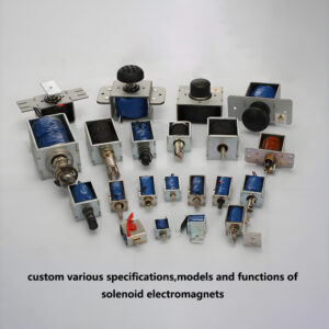










1. What Is a Rotary Electromagnet?
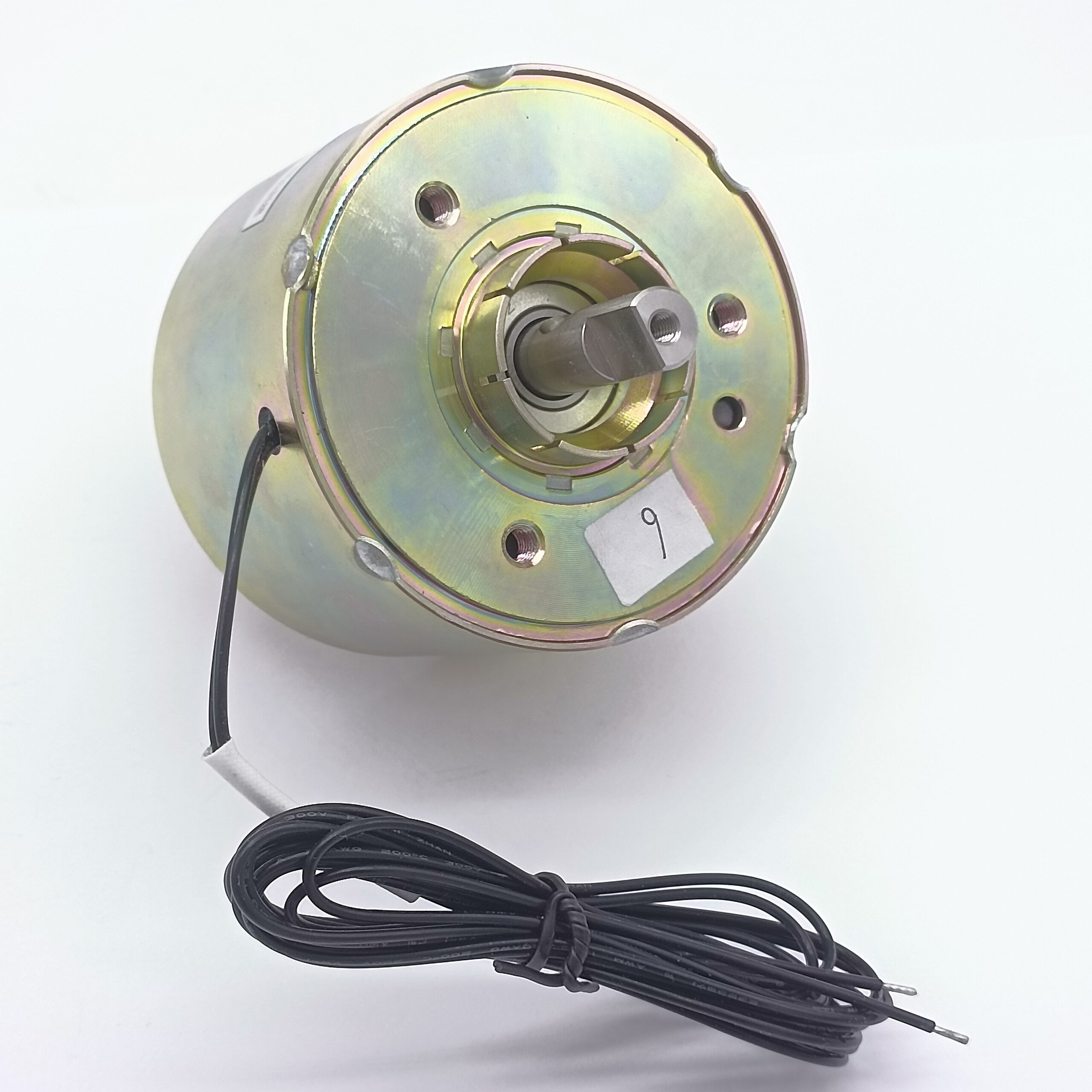
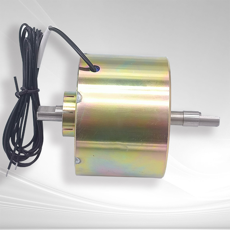
A rotary electromagnet is an electromagnetic actuator that converts electrical energy into controlled rotary mechanical motion. Unlike a conventional linear solenoid, which moves a plunger along a straight axis, a rotary electromagnet generates angular movement around a defined rotational axis. This makes it particularly useful when an automated mechanism needs to rotate, index, latch, switch, unlock, divert, or reposition a component within a limited space.
The basic operating concept is straightforward: when electrical current passes through the actuator’s coil, it creates a magnetic field. The magnetic circuit generates electromagnetic torque that moves a rotor, armature, or specially shaped magnetic element toward a preferred position. Depending on the design, the rotary electromagnet may provide a limited angular movement such as 30°, 45°, 60°, 90°, or another customized angle.
However, designing a reliable rotary electromagnet is considerably more complicated than simply adding a rotational component to a linear solenoid. The magnetic circuit, rotor geometry, air gap, coil parameters, spring mechanism, rotational friction, stopping position, torque-angle relationship, duty cycle, and installation conditions must all work together. For OEM customers, selecting an experienced custom rotary electromagnet manufacturer is therefore essential.
SF has more than 10 years of experience manufacturing customized electromagnets and solenoids. With an experienced engineering team, a 6,000㎡ manufacturing facility, extensive OEM customization experience, and products exported to more than 60 countries and regions, SF provides customized electromagnetic actuator solutions for customers requiring specific force, torque, stroke, size, voltage, lifetime, and environmental performance.
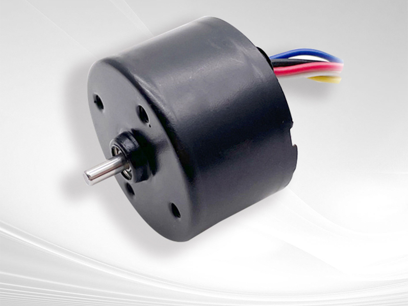
2. Rotary Electromagnet Working Principle: How Does It Produce Rotation?
The working principle of a rotary electromagnet is based on electromagnetic force and the tendency of a magnetic circuit to move toward a lower-reluctance state.
When the coil is energized, current produces magnetic flux through the magnetic circuit. The resulting magnetic field interacts with the rotor or armature and produces torque. The mechanical structure then converts this electromagnetic torque into controlled angular movement.
A simplified relationship can be expressed as:
Electromagnetic Torque ≈ Magnetic Force × Effective Radius
The actual relationship is more complicated because magnetic flux density changes with rotor position, air gap, magnetic saturation, coil current, and magnetic-circuit geometry.
One important characteristic is that rotary electromagnetic torque is generally position-dependent. A rotary electromagnet may produce very different torque at the beginning and end of its angular movement.
For this reason, an engineering specification should not simply say:
“Rotary electromagnet: 90° rotation.”
A more useful specification defines:
- Rated voltage
- Rotation angle
- Starting torque
- Minimum torque
- Holding torque
- Rotation direction
- Return method
- Response time
- Duty cycle
- Maximum current
- Operating temperature
- Required lifetime
This information allows a rotary electromagnet factory to design the magnetic and mechanical systems around the customer’s actual requirements.
3. Rotary Electromagnet vs. Linear Solenoid: What Is the Difference?
A rotary electromagnet and a conventional linear solenoid both use electromagnetic energy, but their mechanical outputs are fundamentally different.
A linear solenoid produces axial movement:
Electrical energy → magnetic field → linear plunger movement
A rotary electromagnet produces angular movement:
Electrical energy → magnetic field → electromagnetic torque → rotary movement
This difference affects almost every aspect of product design.
| Characteristic | Linear Solenoid | Rotary Electromagnet |
|---|---|---|
| Output | Linear | Rotary |
| Main moving component | Plunger | Rotor/armature |
| Typical motion | Push/pull | Angular rotation |
| Key parameter | Force | Torque |
| Typical design concern | Stroke | Rotation angle |
| Mechanical load | Axial | Rotational |
| Return method | Spring/load | Spring, magnetic or mechanical return |
| Typical application | Locking, pushing, valves | Switching, indexing, latching |
| Main curve | Force-stroke | Torque-angle |
Neither technology is universally better.
The correct choice depends on the mechanical movement required by the customer’s equipment. If a mechanism needs to rotate a lever through a defined angle, a rotary electromagnetic actuator can eliminate additional mechanical transmission components and simplify the overall system.
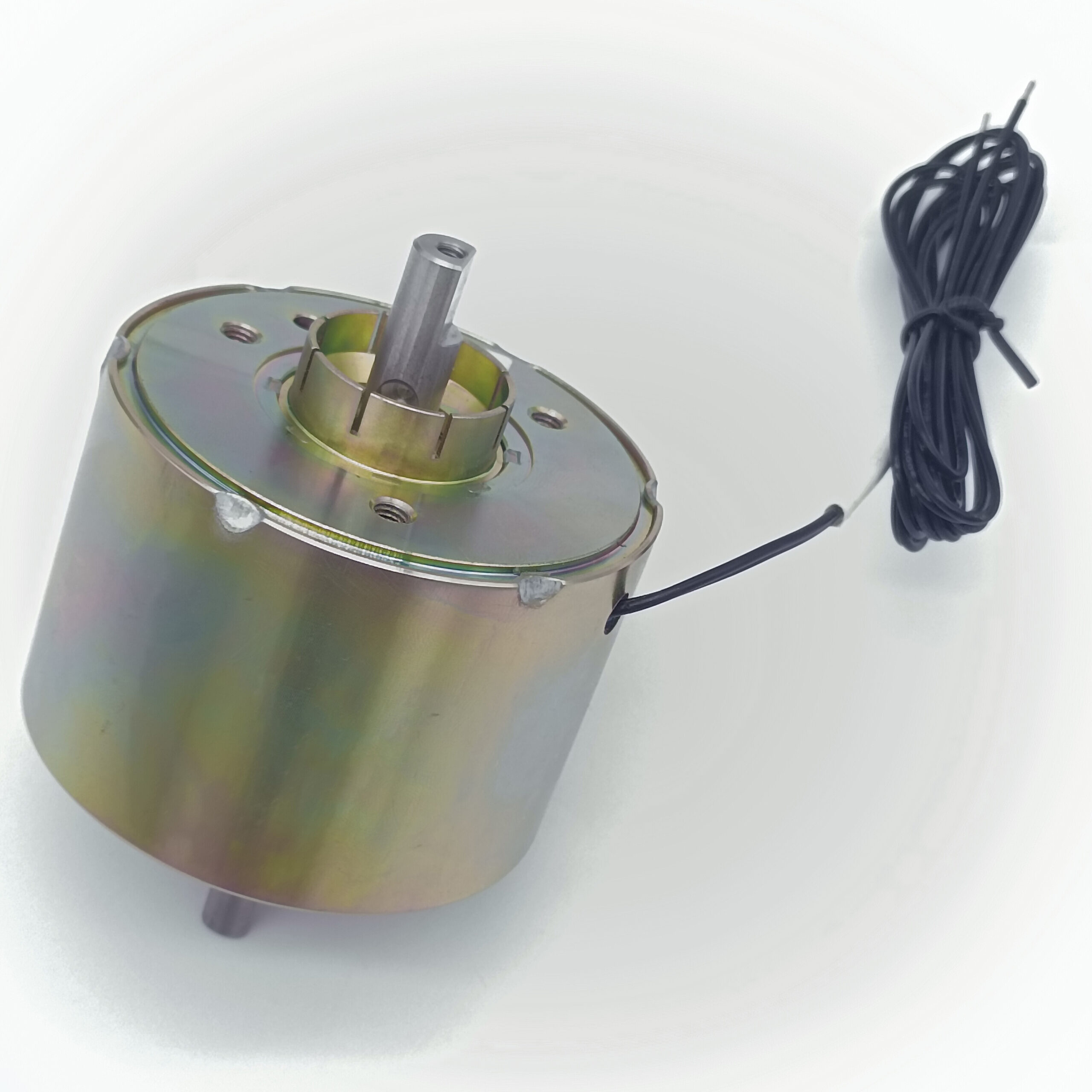

4. Rotary Electromagnet Design: The Magnetic Circuit Is Critical
The magnetic circuit is one of the most important elements in rotary electromagnet design.
A typical magnetic circuit may contain:
- Coil
- Magnetic core
- Rotor or armature
- Pole pieces
- Magnetic housing
- Air gaps
- Flux-return components
The objective is to generate sufficient magnetic flux while minimizing unnecessary magnetic reluctance.
Air gap is particularly important.
A larger air gap generally increases magnetic reluctance and reduces magnetic coupling. A smaller and properly controlled air gap can increase electromagnetic performance, but excessive reduction may introduce mechanical interference, manufacturing sensitivity, or sticking.
Therefore, a professional custom rotary electromagnet manufacturer must balance:
Magnetic performance + manufacturing tolerance + mechanical clearance + durability
The geometry of the rotor and pole faces also determines how torque changes with angular position.
This is why two rotary electromagnets with identical voltage and coil resistance can have very different torque characteristics.
5. Rotary Electromagnet Torque and Angle: Why the Torque Curve Matters
One of the most important parameters when specifying a rotary electromagnet is the torque-angle relationship.
Torque should be evaluated across the complete operating angle rather than at only one position.
For example:
| Rotor Position | Torque Requirement |
|---|---|
| 0° | ≥ X mN·m |
| 15° | ≥ X mN·m |
| 30° | ≥ X mN·m |
| 45° | ≥ X mN·m |
| 60° | ≥ X mN·m |
| 90° | ≥ X mN·m |
The actual values depend entirely on the application.
The customer should also consider the external mechanical load.
The required actuator torque can be thought of as:
Required Torque = Load Torque + Friction Torque + Acceleration Torque + Safety Margin
If the rotary electromagnet is required to move a mechanical lever quickly, acceleration torque becomes important.
If the mechanism contains bearings, gears, seals, or friction surfaces, those loads must also be included.
An experienced rotary electromagnet factory should therefore evaluate the complete torque-angle profile instead of promising only a nominal maximum torque.
6. Rotary Electromagnet Coil Design: Voltage, Current, Heat, and Response
The coil determines how the rotary electromagnet generates its magnetic field.
Important coil parameters include:
- Rated voltage
- Wire diameter
- Number of turns
- Resistance
- Inductance
- Current
- Power consumption
- Insulation class
- Duty cycle
For example, a low-voltage battery-powered device may require extremely low power consumption, while an industrial actuator may prioritize high torque and rapid response.
Increasing coil current can increase magnetic force, but it also increases heat generation.
This creates a fundamental engineering trade-off:
Higher current → potentially higher torque → more heat
The coil therefore needs to be designed according to the actual duty cycle.
A rotary electromagnet operating for 100 ms every few minutes is thermally very different from an actuator energized continuously.
For demanding applications, SF engineers can optimize the electromagnetic design rather than simply increasing coil power.
7. Rotary Electromagnet Response Time: How to Achieve Fast Rotation
Response time is another important performance parameter.
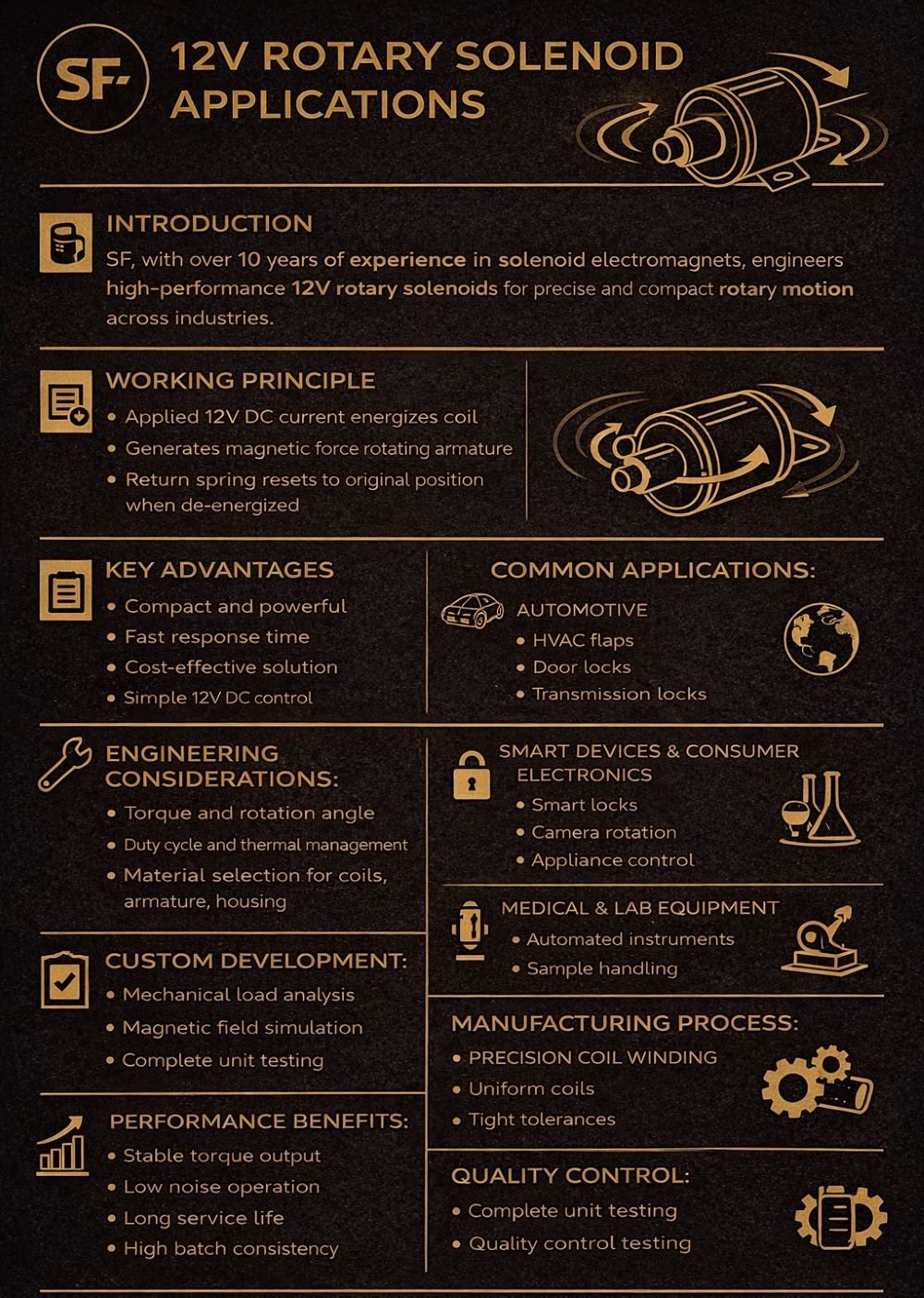
A rotary electromagnet may need to rotate within milliseconds in applications such as:
- Automated switching
- Printing equipment
- Sorting systems
- Industrial automation
- Office equipment
- Electronic mechanisms
Response time depends on several interacting factors:
Electrical time constant + magnetic force/torque + rotor inertia + friction + load + return mechanism
The electrical side is influenced by coil resistance and inductance.
The mechanical side is influenced by:
- Rotor mass
- Moment of inertia
- Load torque
- Spring force
- Friction
- Rotation angle
- Mechanical stops
A higher coil power does not automatically guarantee the fastest actuator.
In some applications, a lower-inertia rotor combined with optimized magnetic geometry can produce better dynamic performance without dramatically increasing power consumption.
A sophisticated custom rotary solenoid manufacturer therefore considers both electromagnetic and mechanical dynamics.
8. Rotary Electromagnet Return Mechanisms and Position Control
A rotary electromagnet can be designed with different return strategies depending on the application.
Spring Return
The actuator rotates when energized and returns when power is removed.
Advantages include:
- Simple control
- Predictable return
- Low control complexity
- Suitable for many switching mechanisms
Dual-Action or Two-Direction Designs
The actuator can be controlled in different directions through a more complex magnetic or mechanical design.
Magnetic Latching
The actuator can maintain a position without continuous power in appropriately designed configurations.
This can be particularly valuable for battery-operated equipment.
External Mechanical Return
The customer’s machine provides the return force.
This can reduce actuator complexity but requires careful integration.
Selecting the appropriate return method depends on:
- Required holding torque
- Energy consumption
- Response time
- Available space
- Operating frequency
- Safety requirements
The return mechanism should therefore be specified during the early engineering stage.
9. Rotary Electromagnet Applications: Where Are They Used?
The versatility of the rotary electromagnet makes it suitable for numerous industries.
Industrial Automation
Rotary electromagnetic actuators can operate:
- Mechanical switches
- Diverting mechanisms
- Indexing systems
- Small gates
- Positioning mechanisms
Office Equipment
Applications include:
- Paper routing
- Document handling
- Printer mechanisms
- Copier mechanisms
- Locking mechanisms
Medical Equipment
Precision rotary actuators can be used in:
- Fluid-control mechanisms
- Small positioning systems
- Automated laboratory equipment
- Medical instrument mechanisms
Low noise, reliable positioning, compact dimensions, and controlled movement can be particularly important in these applications.
Automotive
Rotary electromagnetic actuators may be integrated into:
- Latching mechanisms
- HVAC systems
- Seat mechanisms
- Transmission-related mechanisms
- Valve-control systems
Vending and Payment Equipment
They can be used for:
- Product release mechanisms
- Door locking
- Coin-routing mechanisms
- Internal switching
Consumer Appliances
Potential applications include:
- Appliance locks
- Switching mechanisms
- Valve mechanisms
- Small automatic positioning systems
This broad application range is one reason demand for customized rotary electromagnetic actuators continues to grow.

10. Rotary Electromagnet Customization: What Can Be Customized?
A major advantage of working with a custom rotary electromagnet manufacturer is the ability to design the actuator around the customer’s equipment rather than forcing the equipment to fit a standard component.
Customization can include:
Electrical Parameters
- 5 VDC
- 12 VDC
- 24 VDC
- AC configurations where appropriate
- Custom resistance
- Custom power consumption
Mechanical Parameters
- Rotation angle
- Shaft configuration
- Mounting holes
- Housing dimensions
- Shaft diameter
- Connector position
- Mechanical stop
Performance
- Starting torque
- Holding torque
- Response time
- Return time
- Duty cycle
- Noise level
- Lifetime
Environmental
- Temperature
- Humidity
- Dust
- Corrosion
- Vibration
The advantage is that the final actuator can be optimized for the customer’s actual assembly conditions.
11. Rotary Electromagnet Material Selection and Surface Treatment
Materials influence both electromagnetic performance and mechanical durability.
Magnetic components require materials with appropriate magnetic properties.
Other components may require:
- High mechanical strength
- Wear resistance
- Corrosion resistance
- Low friction
- Temperature resistance
The rotor and shaft may also require appropriate surface treatment.
Depending on the application, possible treatments include different plating or coating approaches designed to improve corrosion resistance or surface durability.
Material selection should therefore consider the complete operating environment.
For example, an actuator operating inside a humid industrial machine may require different surface protection from one installed inside a clean office device.
A professional electromagnet factory should be able to recommend materials according to the customer’s combination of magnetic, mechanical, thermal, and environmental requirements.
12. Rotary Electromagnet Noise, Friction, and Lifetime
In applications such as medical equipment, office machines, laboratory instruments, and consumer products, mechanical noise can be an important specification.
Noise can originate from:
- Rotor impact
- Mechanical stops
- Spring vibration
- Bearing or guide friction
- Housing resonance
- Rapid electromagnetic movement
Possible solutions include:
- Optimized mechanical stops
- Damping materials
- Controlled rotor acceleration
- Better alignment
- Reduced mechanical clearance
- Optimized spring characteristics
- Improved surface finish
Lifetime is also strongly related to these factors.
A rotary electromagnet intended for hundreds of thousands or millions of cycles needs careful control of:
Friction + wear + impact + temperature + material + lubrication + mechanical alignment
Therefore, lifecycle testing should be considered during product development rather than after mass production has already begun.
13. How to Choose the Right Rotary Electromagnet for Your Application
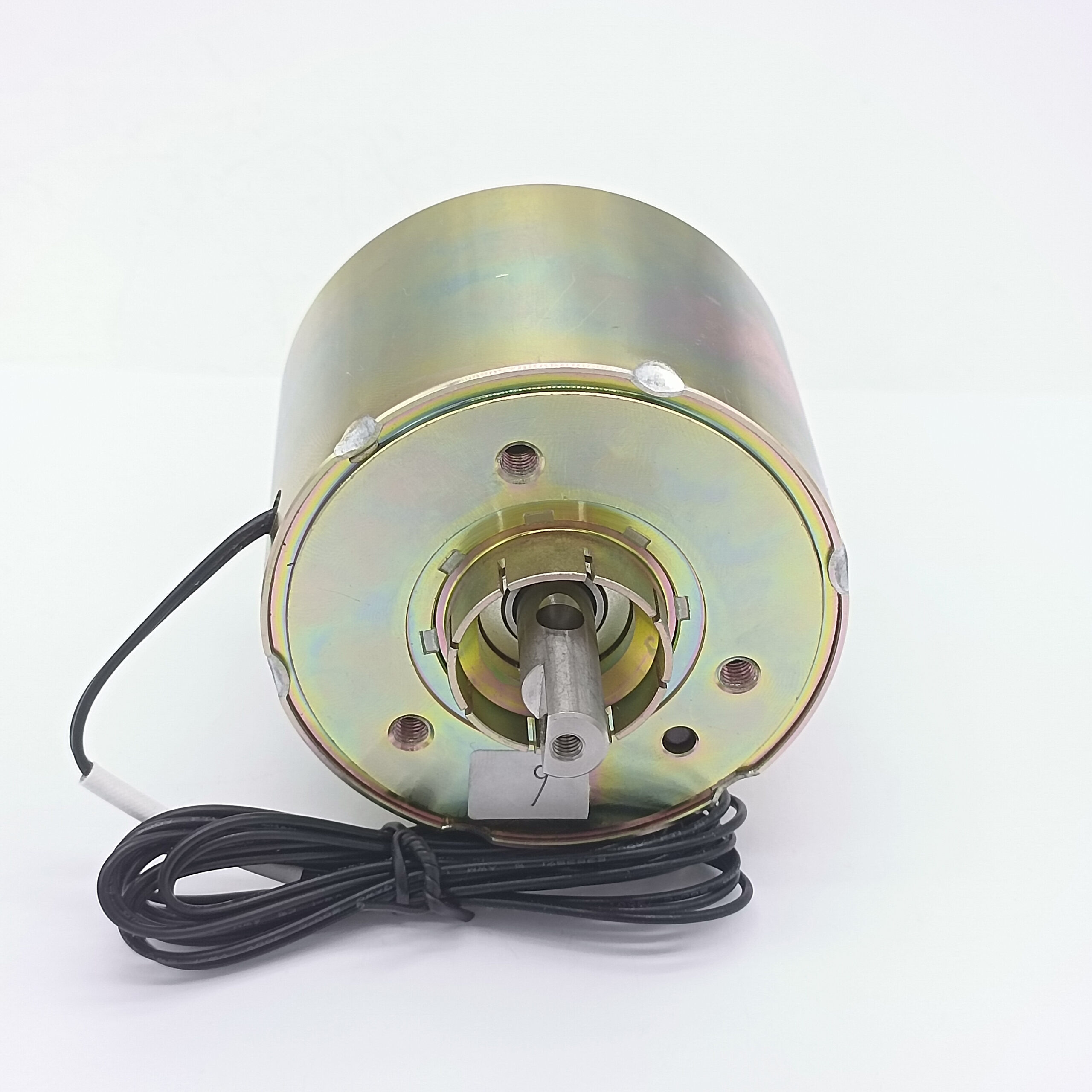
Before selecting a rotary electromagnet, engineers should define the complete application requirements.
A useful selection checklist includes:
| Parameter | Key Question |
|---|---|
| Voltage | What is the available operating voltage? |
| Torque | How much torque is required? |
| Angle | How many degrees must it rotate? |
| Load | What mechanical load must it move? |
| Speed | How quickly must it rotate? |
| Duty Cycle | How frequently is it energized? |
| Space | What is the maximum envelope? |
| Return | Is spring return required? |
| Noise | Is acoustic performance critical? |
| Temperature | What is the operating temperature? |
| Life | How many cycles are required? |
| Environment | Is humidity, dust, vibration, or corrosion involved? |
| Installation | What mounting and shaft configuration is required? |
One of the most common mistakes is selecting an actuator based only on voltage and maximum torque.
A technically correct selection requires the torque-angle curve, dynamic requirements, thermal conditions, mechanical interface, and duty cycle to be considered together.
14. How to Choose a Rotary Electromagnet Factory
The manufacturer can have a major impact on the final performance of a custom rotary electromagnet.
When evaluating a rotary electromagnet factory, OEM buyers should examine at least the following eight dimensions:
1. Engineering Capability
Can the supplier design the magnetic circuit rather than simply assemble standard components?
2. Prototype Development
Can the manufacturer quickly produce prototypes and make engineering modifications?
3. Magnetic Testing
Can the supplier measure torque, force, current, and electromagnetic performance?
4. Precision Manufacturing
Can critical air gaps, shaft dimensions, and magnetic components be consistently produced?
5. Coil Manufacturing
Does the factory have controlled coil winding and electrical testing?
6. Quality Control
Are incoming materials, in-process components, and finished actuators inspected?
7. Mass Production
Can the supplier maintain consistent performance across large production batches?
8. Application Support
Can engineers help solve problems that occur when the actuator is installed in the customer’s equipment?
For OEM customers, these factors are generally more meaningful than simply comparing unit prices.
A low-cost actuator that requires repeated redesigns, has inconsistent torque, or fails during final assembly can create a much higher total cost.
15. Why SF Is a Strong Choice for Custom Rotary Electromagnet Projects
SF is a professional customized electromagnet and solenoid manufacturer with more than 10 years of manufacturing experience.
Our experienced engineering team works with customers to translate application requirements into practical electromagnetic actuator designs.
SF operates a 6,000㎡ manufacturing facility, providing the production capacity required for both prototype development and larger-volume OEM orders.
Our customization capabilities can cover:
- Rotary electromagnets
- Rotary solenoids
- Linear solenoids
- Push-pull solenoids
- Latching solenoids
- Electromagnets
- Custom electromagnetic actuators
For rotary applications, our engineering approach can consider:
Torque → Rotation Angle → Air Gap → Magnetic Circuit → Coil → Spring → Friction → Thermal Performance → Lifetime
This integrated approach is important because changing one parameter can affect another.
For example, increasing torque may require more magnetic flux, which can increase coil power and temperature. Reducing the actuator size can reduce available magnetic area and thermal dissipation. Increasing spring force can improve return performance but require greater electromagnetic torque.
The engineering objective is therefore not simply to maximize one specification.
It is to achieve the best overall performance within the customer’s size, voltage, cost, temperature, and lifetime constraints.
SF has helped many brand customers develop customized electromagnet solutions and exports products to more than 60 countries and regions.
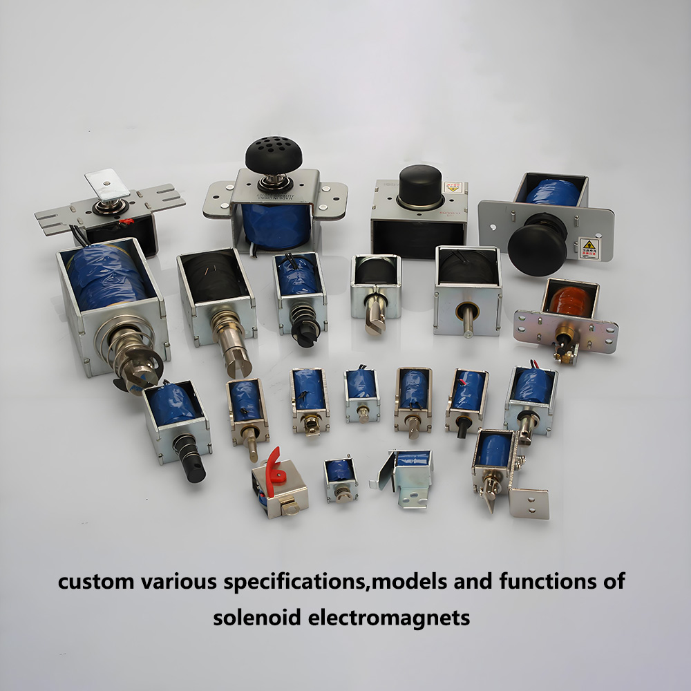
A Rotary Electromagnet Is a System, Not Just a Coil and Rotor
A rotary electromagnet is a compact electromagnetic actuator capable of converting electrical energy into controlled rotary motion. Its applications range from industrial automation and automotive systems to medical equipment, office machines, vending equipment, appliances, and specialized OEM mechanisms.
However, reliable rotary performance depends on more than rated voltage or maximum torque.
The most important engineering dimensions include:
- Working principle and magnetic circuit
- Torque-angle characteristics
- Rotation angle
- Coil design
- Response speed
- Rotor inertia
- Return mechanism
- Air-gap control
- Material selection
- Friction and wear
- Noise and vibration
- Thermal performance
- Environmental resistance
- Lifecycle
- Manufacturing consistency
For OEM applications, the right actuator should be selected based on the complete mechanical and electrical system rather than one isolated specification.
A capable custom rotary electromagnet manufacturer should also be involved early in the design process. Early engineering collaboration makes it easier to optimize the magnetic circuit, coil, rotor geometry, spring, mounting structure, and manufacturing tolerances before the product enters mass production.
With more than 10 years of experience, an experienced engineering team, a 6,000㎡ manufacturing facility, extensive customization capabilities, and customers across 60+ countries and regions, SF provides a complete manufacturing solution for customers seeking reliable customized rotary electromagnets and solenoid actuators.
Quick Reference: Rotary Electromagnet Selection Guide
| Application Requirement | Recommended Design Focus |
|---|---|
| High torque | Magnetic circuit + air-gap optimization |
| Small size | Compact magnetic design + thermal optimization |
| Fast response | Low inertia + optimized coil + drive strategy |
| Low power | Efficient magnetic circuit + optimized coil |
| Battery operation | Latching/low-power configuration where applicable |
| High cycle life | Low friction + wear-resistant materials |
| Low noise | Damping + controlled impact + alignment |
| High temperature | Coil insulation + material + thermal design |
| Industrial environment | Corrosion/vibration/environmental protection |
| Precision equipment | Tight dimensional and torque control |
| Mass production | SPC + automated testing + process control |
| OEM integration | Customized mounting, shaft, angle, voltage and performance |
Custom all kinds of electromagnet, contact SF electromagnet factory whatsapp +86 189 0261 1680