Last Updated on 2025-11-14 by SolenoidFactory
As smart home technology evolves, the smart lock electromagnet has become one of the most essential components in ensuring secure, reliable, and energy-efficient locking performance. Modern smart locks depend on precisely engineered electromagnets to control latch movement, holding force, actuation timing, and long-term durability.
For more than 10 years, SF has specialized in the custom design and manufacturing of solenoids and electromagnets, serving global brands across security, IoT, commercial access systems, industrial automation, and consumer electronics. One of our most successful engineering collaborations has been with a leading (confidential) smart lock manufacturer who required a high-performance custom smart lock electromagnet designed for long service life, quiet operation, strict energy limits, and compact structural constraints.
This article provides a detailed technical case study of how SF engineered a custom smart lock electromagnet solution, from initial requirements to prototyping, performance validation, and final mass production.
1. Understanding the Functional Requirements of a Smart Lock Electromagnet
Before developing a next-generation smart lock electromagnet, it is necessary to understand the unique operational demands of digital locking systems. Unlike traditional solenoids, a smart lock electromagnet must satisfy a combination of mechanical, electrical, thermal, and environmental constraints that collectively determine safety and user experience.
1.1 Miniaturization and Compact Space Usage
Smart locks have extremely limited internal space due to:
Motor or drive components
Wireless communication modules
Battery compartments
Mechanical latching systems
Structural housings
This means a smart lock electromagnet must deliver a high holding force within a very compact coil and plunger structure.
1.2 Low-Power Operation for Battery Efficiency
Most smart locks are battery-powered. The electromagnet must therefore:
Operate efficiently under 3–6V DC
Minimize energy draw during each actuation
Sustain performance even under battery voltage decay
A poorly designed smart lock electromagnet can shorten battery life dramatically, leading to poor user reviews and increased maintenance.
1.3 Quiet and Smooth Actuation
Users expect:
Silent or near-silent unlocking
Smooth movement with no metal clicking
Zero mechanical vibration
Achieving this requires:
Precision fit tolerances
Optimized plunger mass
Correct spring selection
Coil winding optimization
1.4 High Reliability and Long Cycle Life
A smart lock may be opened 10,000–50,000+ times yearly, so its electromagnet must handle:
High cycle load
Consistent force output
Non-stop daily use
Indoor/outdoor temperature changes
1.5 Safety Requirements
A smart lock electromagnet is part of a security system. Therefore it must:
Deliver predictable holding force
Avoid overheating
Maintain stable magnetic performance over time
Continue functioning when partially degraded
This is why SF uses premium core materials, high-temperature coils, and advanced process controls.
2. Project Brief: The Customer’s Requirements for a Custom Smart Lock Electromagnet
A globally recognized smart lock brand approached SF with a clear but challenging requirement:
Customer Requirements Summary
Ultra-compact electromagnet suitable for a thin smart lock housing
Fast actuation under 20–40 milliseconds
Silent operation, less than 30 dB
Low power consumption, optimized for long battery life
High temperature resistance for outdoor summer installations
Ability to sustain 100,000+ life cycles
Stable force output throughout battery discharge curve
Corrosion-resistant materials for long-term durability
Tight tolerances for plunger movement
High safety margin for continuous lock reliability
Meeting the customer’s expectations required a full engineering collaboration, advanced simulation, and multiple rounds of prototyping.
3. SF’s Technical Development Process for the Smart Lock Electromagnet
SF follows a structured engineering methodology for designing every smart lock electromagnet, ensuring consistent quality, repeatability, and performance.
3.1 Magnetic Field Simulation & Force Modeling
Our R&D engineers first performed electromagnetic simulation using:
Finite element analysis (FEA)
Magnetic flux density modeling
Plunger force curve prediction
Energy efficiency optimization
The goal was to create a smart lock electromagnet that delivers maximum force at minimum current.
Simulation allowed us to:
Reduce unnecessary copper windings
Optimize core geometry
Improve magnetic saturation behavior
Minimize heat buildup
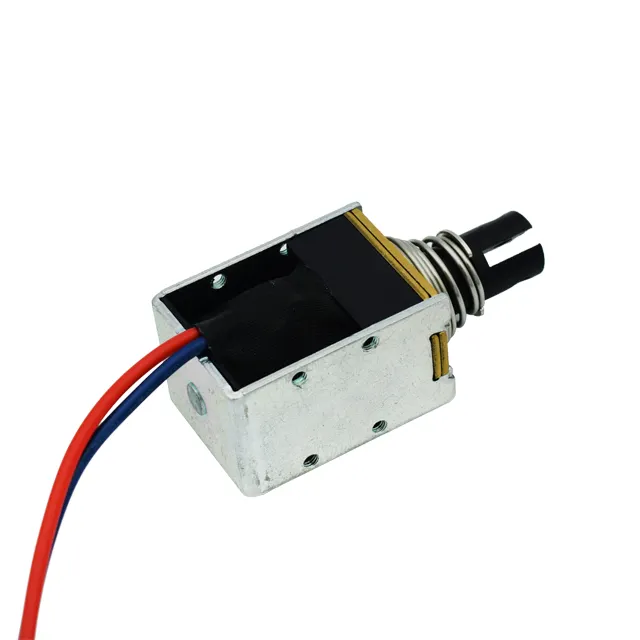
3.2 Coil Design for Low-Power Performance
We engineered a custom coil that balanced:
Wire gauge
Number of turns
Resistance
Current efficiency
Heat rise limits
This produced a smart lock electromagnet coil with:
Faster response time
Lower energy consumption
Better temperature stability
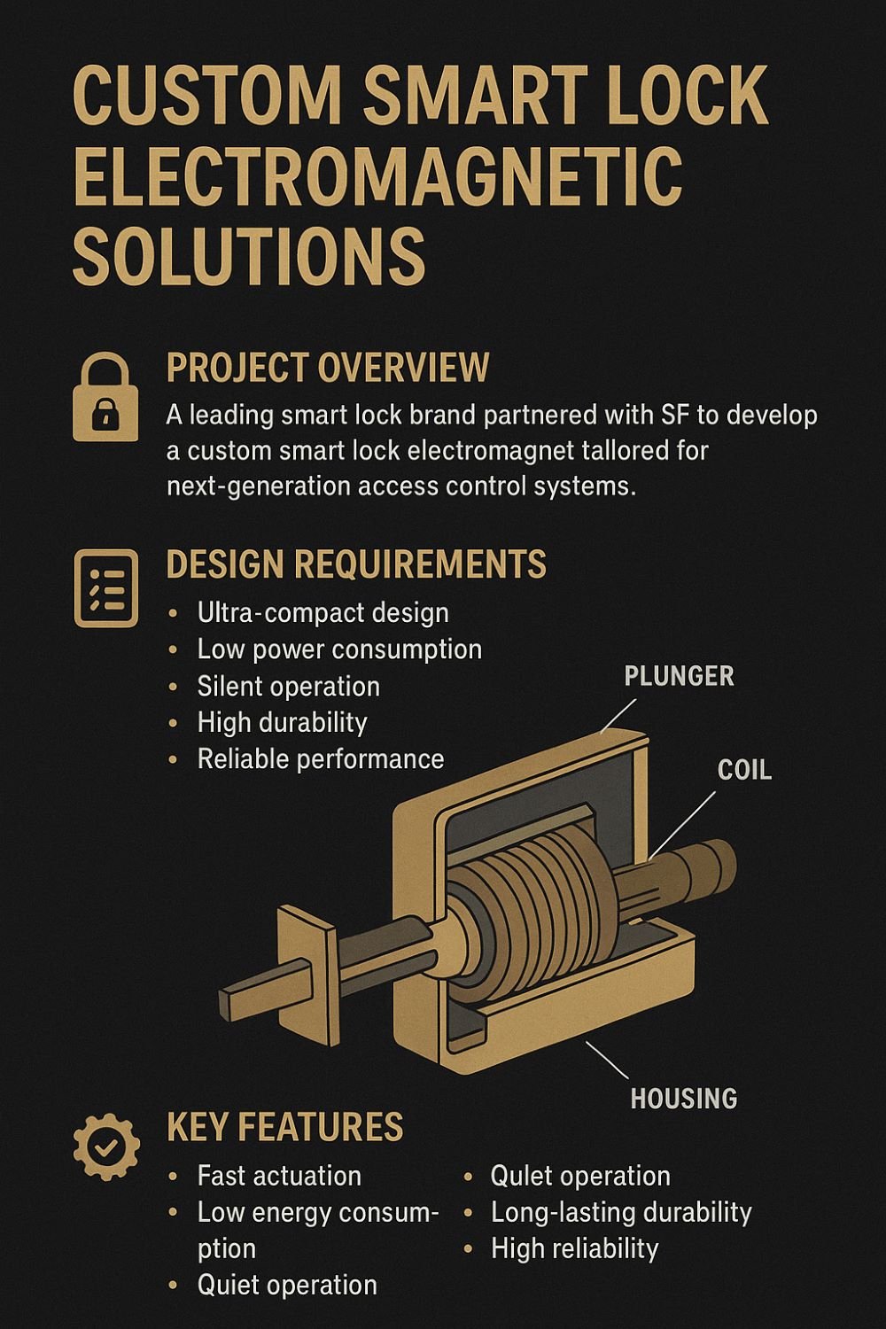
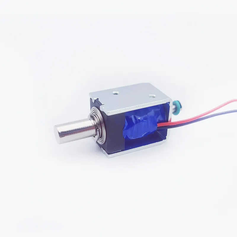
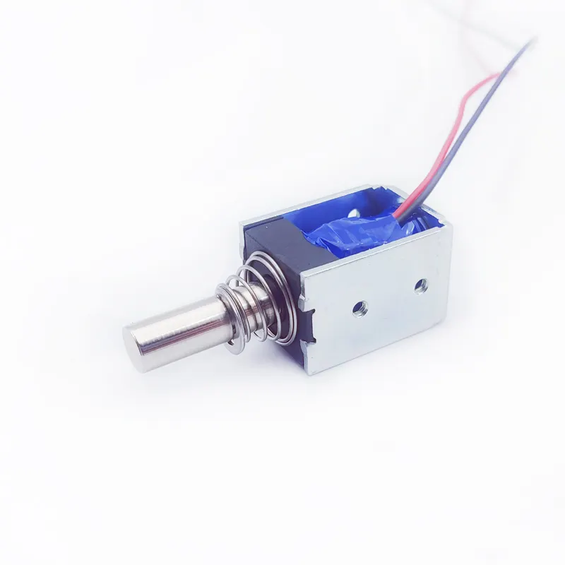
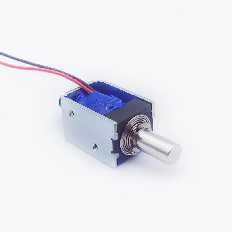
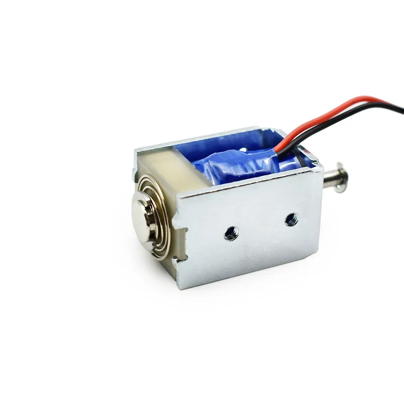
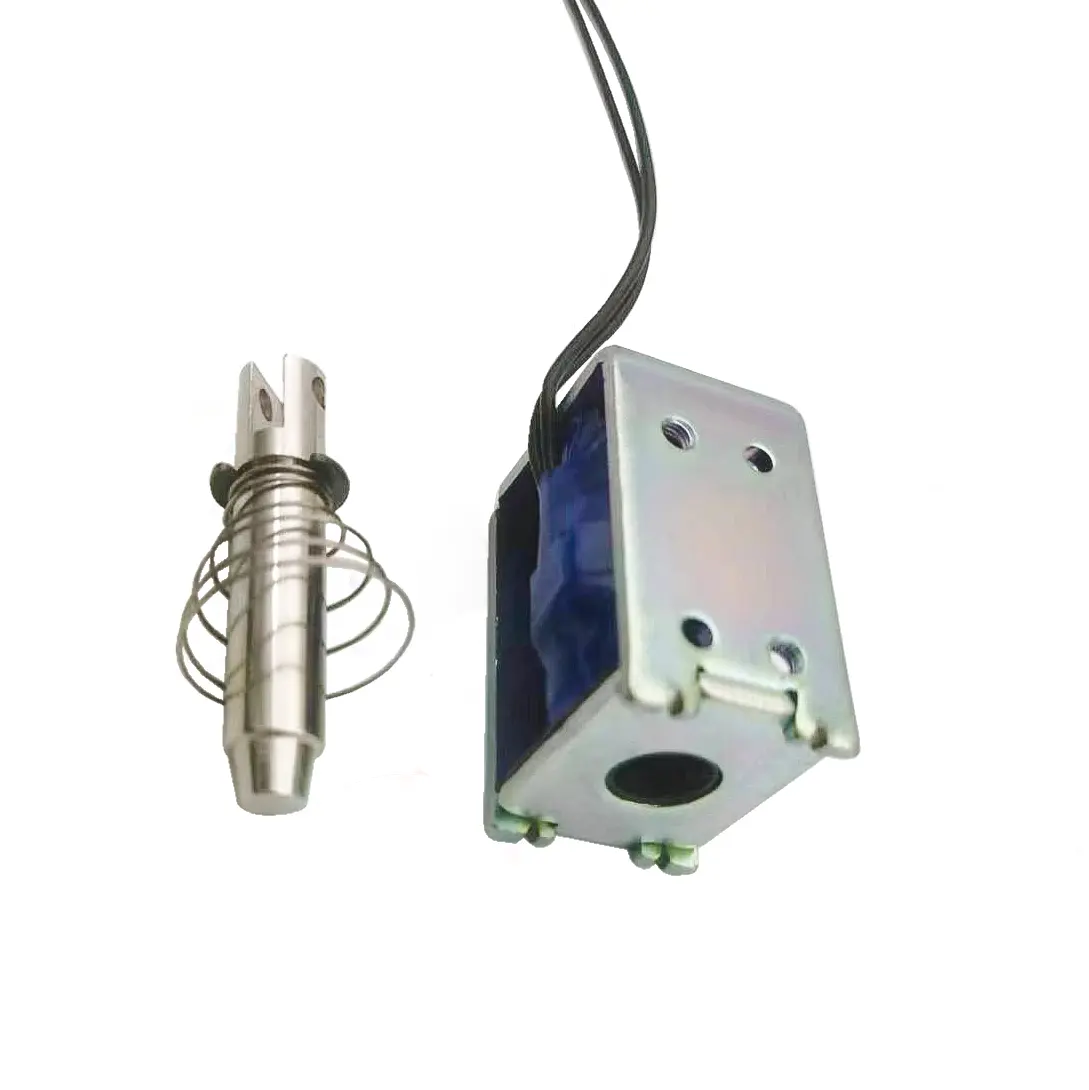
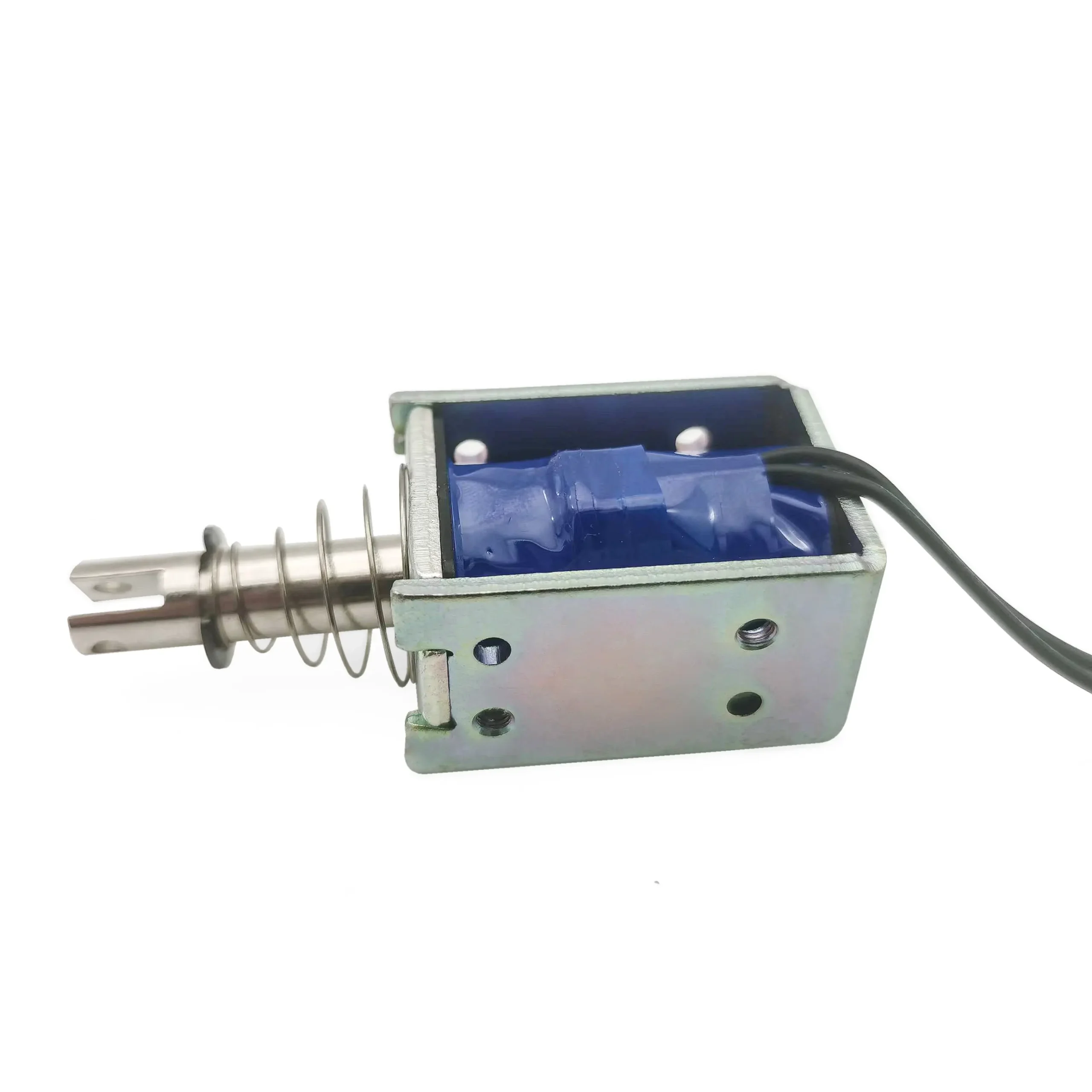
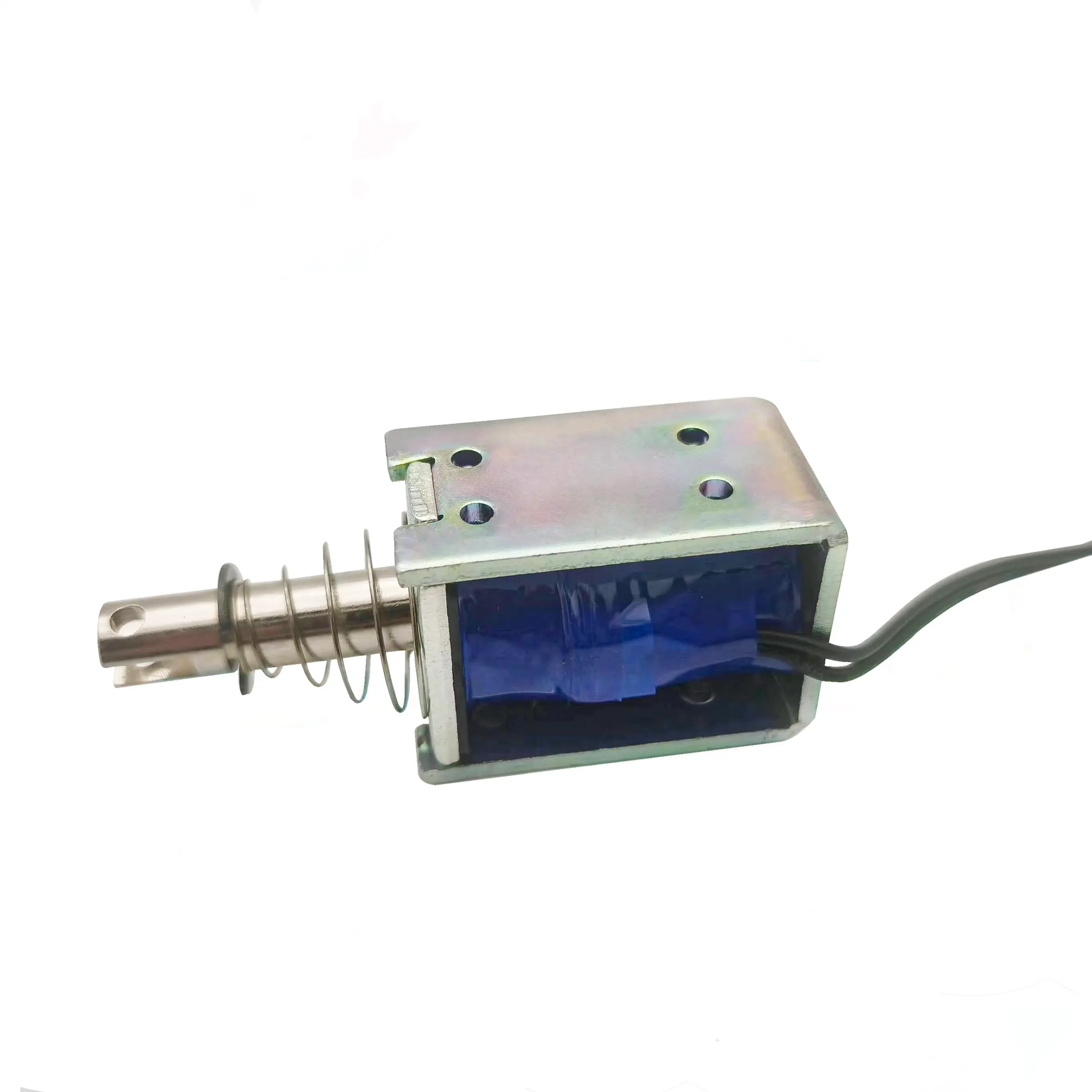
3.3 Precision Plunger and Housing Engineering
The plunger system is the mechanical heart of any smart lock electromagnet.
SF utilized:
High-precision CNC machining
Surface finishing to reduce friction
Tolerance control within ±0.02mm
Stainless steel alloy resistant to wear
The result was smooth, silent, repeatable linear motion.
3.4 Noise Reduction Techniques
To meet the <30 dB requirement, SF applied:
Sound-dampening coatings
Low-impact spring design
Anti-vibration housing
Soft-close plunger head geometry
This produced a smart lock electromagnet that operates almost silently in residential environments.
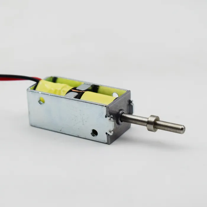
3.5 Thermal Management & High-Temperature Materials
Smart locks installed outdoors face:
Summer heat
Direct sunlight
Enclosed space thermal buildup
To handle this, we used:
High-temperature enameled wire
Heat-resistant bobbin materials
Magnetic steel with stable permeability
Our final design maintained performance even at 80°C ambient temperature.
3.6 Lifecycle Testing and Durability Optimization
The customer required 100,000+ cycles, but SF engineered for 200,000 cycles to ensure extra safety margin.
Testing included:
Continuous cycle fatigue testing
Voltage drop simulation
Elevated temperature aging
Corrosion resistance testing
Mechanical shock and vibration tests
The final smart lock electromagnet exceeded all durability targets.
4. Prototype Development and Validation
After simulation and design approval, SF produced multiple prototype batches for validation.
4.1 Batch A — Baseline Functionality
The first batch confirmed:
General force output
Fit into housing
Basic performance
4.2 Batch B — Silent Operation Testing
This batch focused on noise reduction and plunger smoothness.
4.3 Batch C — Power Optimization
Here we adjusted:
Coil resistance
Winding strategy
Energy consumption efficiency
4.4 Batch D — Final Engineering Refinement
This was the final production-ready version, optimized for:
Force stability
Minimal heat rise
Maximum cycle life
Strong magnetic retention
5. Final Smart Lock Electromagnet Specification
(Representative specifications; confidential customer details excluded.)
Electrical Specifications
Voltage: 3–6V DC
Current: 0.3–0.6A
Coil Resistance: Customized per model
Actuation Time: <40ms
Mechanical Specifications
Stroke: 1–4mm depending on model
Holding Force: 3–15N
Materials: Stainless steel, soft magnetic alloy
Environmental
Working Temperature: -10°C to 80°C
Humidity: up to 95%
Corrosion Resistance: IP-grade housing optional
Lifecycle
Tested to 200,000+ cycles
6. How the Smart Lock Electromagnet Performs in Real Applications
Once integrated into the customer’s smart lock product, the electromagnet delivered exceptional results.
6.1 Faster and Smoother Unlocking
The improved plunger geometry and reduced friction delivered:
Instantaneous latch disengagement
Smoother user experience
6.2 Lower Power Consumption
The optimized coil reduced energy use, extending battery life by 18–25%.
6.3 Silent Operation
Users reported significantly quieter unlocking — a major competitive advantage.
6.4 Higher Reliability and Safety
Long-term stability improved due to:
Wear-resistant materials
Stronger magnetic circuit design
Premium coil insulation
The final smart lock electromagnet improved overall product reliability.
7. Manufacturing Process Control at SF
To ensure consistent quality, every final batch of the smart lock electromagnet passed:
Incoming Material Inspection
Core metal composition check
Copper wire inspection
Coil insulation verification
Housing tolerance measurement
In-Process QC
Coil resistance testing
Plunger smoothness measurement
Magnetic force verification
Final QC
Noise test
Vibration test
Functional test
High/low temperature performance
8. Why Smart Lock Brands Choose SF
Smart lock manufacturers trust SF because:
✔ Over 10 years of electromagnet engineering
✔ Advanced simulation and R&D capabilities
✔ Customization for unique space and force requirements
✔ Strict QC and reliability testing
✔ Competitive pricing with superior performance
✔ Scalable production capacity
SF provides a complete smart lock electromagnet solution, not just a component.
SF Leads the Future of Smart Lock Electromagnet Innovation
As smart homes become more widespread, the demand for high-performance smart lock electromagnet technology continues to grow. SF’s ability to engineer advanced, compact, low-power, silent, and durable electromagnets gives smart lock manufacturers a powerful competitive advantage.
This case study demonstrates SF’s full engineering capability:
Technical simulation
Custom design
Prototype optimization
Performance validation
Mass production quality stability
If your brand is developing next-generation smart locking products, SF is ready to provide custom smart lock electromagnet solutions that meet the highest standards of reliability and performance.
Custom all kinds of electromagnet, contact SF electromagnet factory whatsapp +86 189 0261 1680


